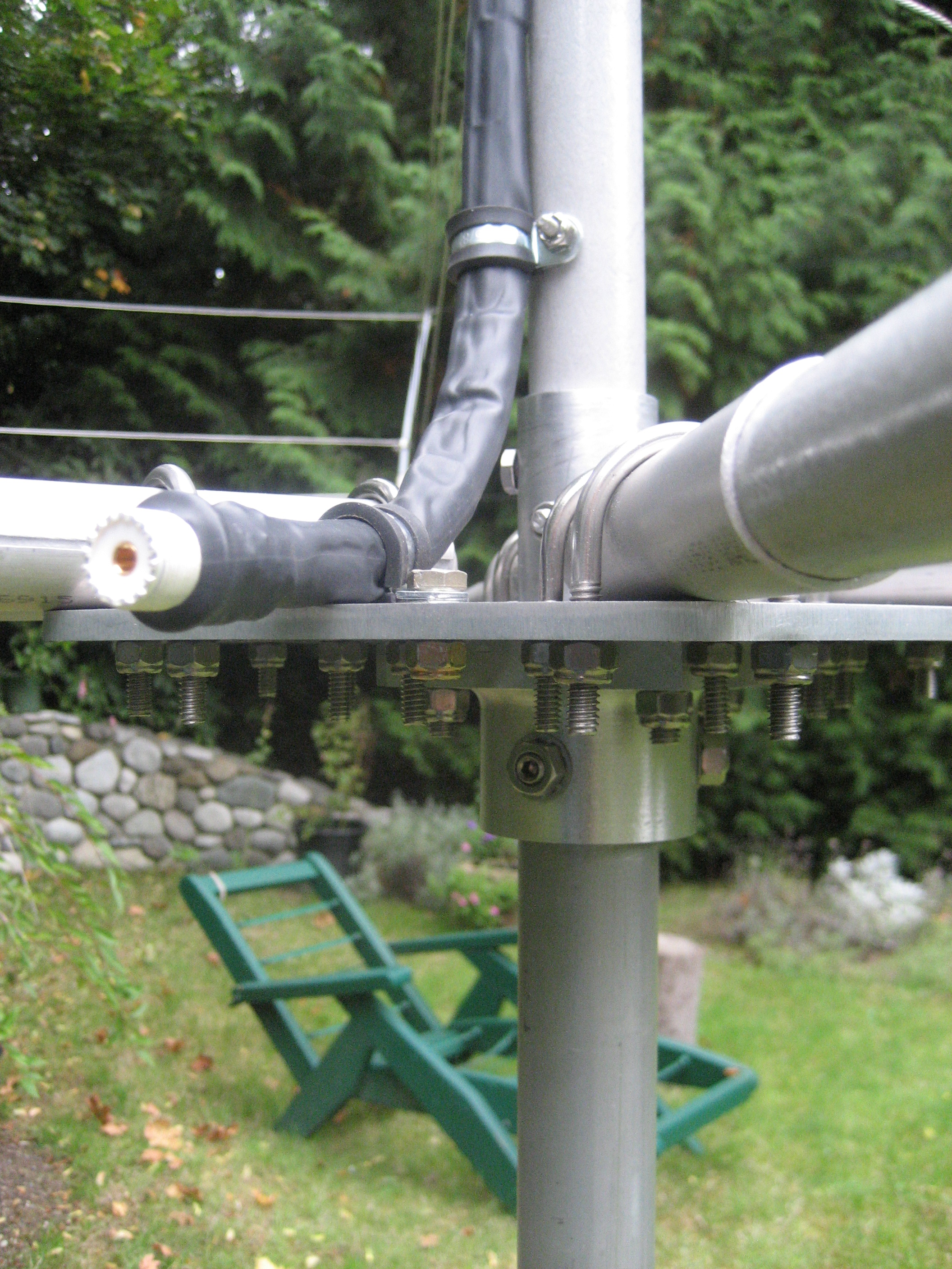
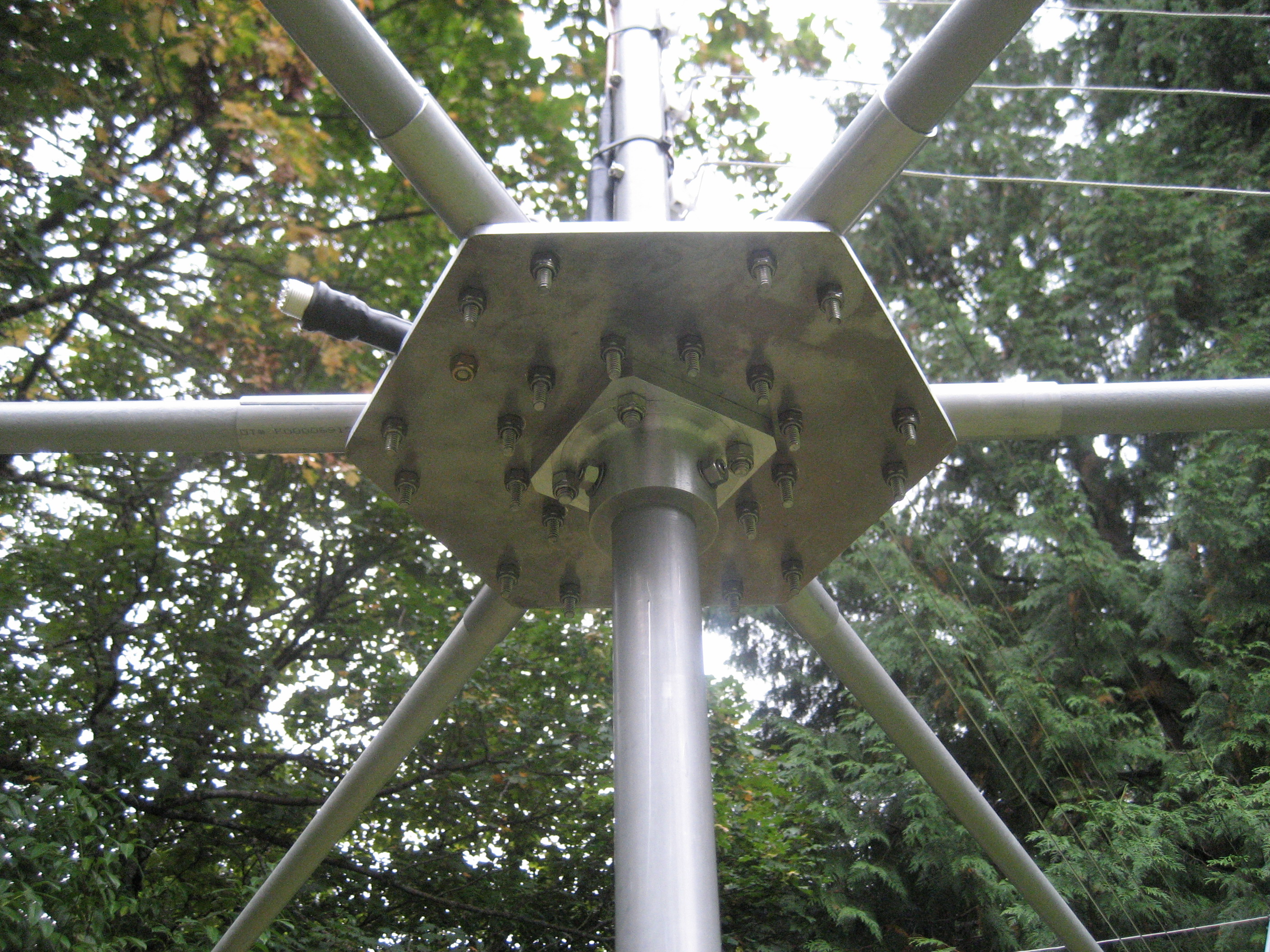
This page shows the construction of my five band (20 through 10 meter) broadband hexbeam. The beam was designed by G3TXQ, and extensive design and testing notes are available here. I've used the design with minimal modifications. My construction methods largely follow notes by K4KIO.
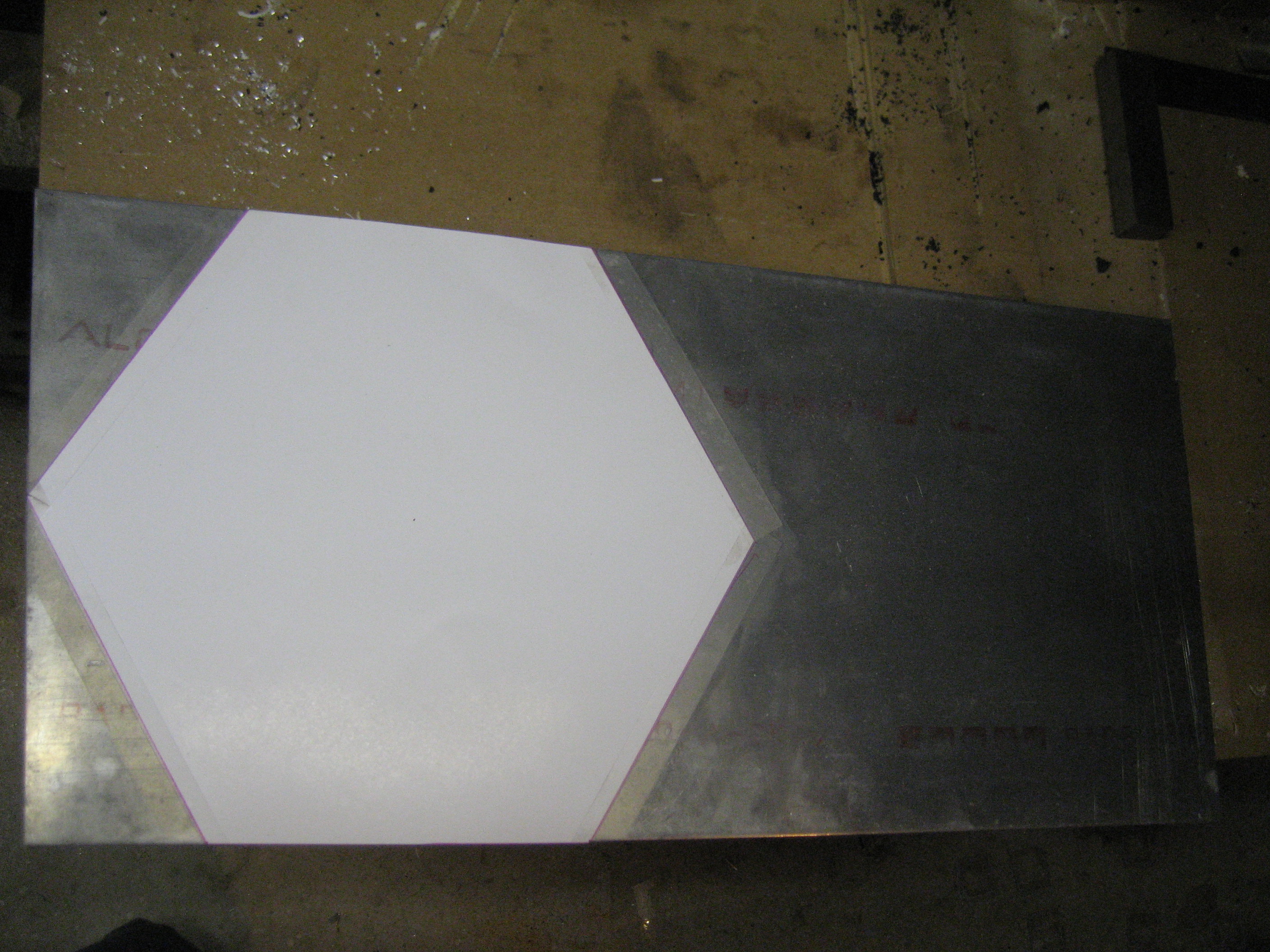
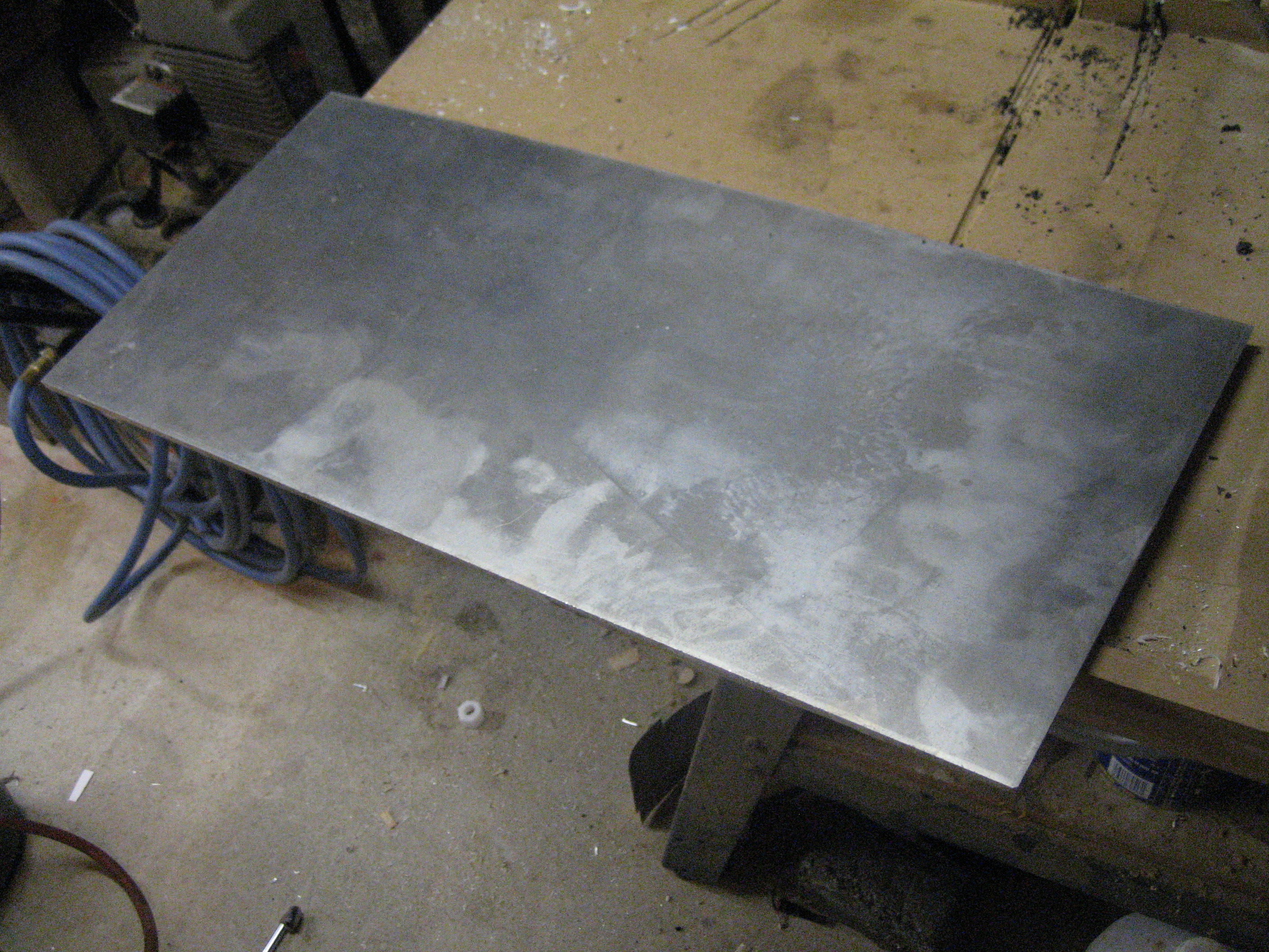
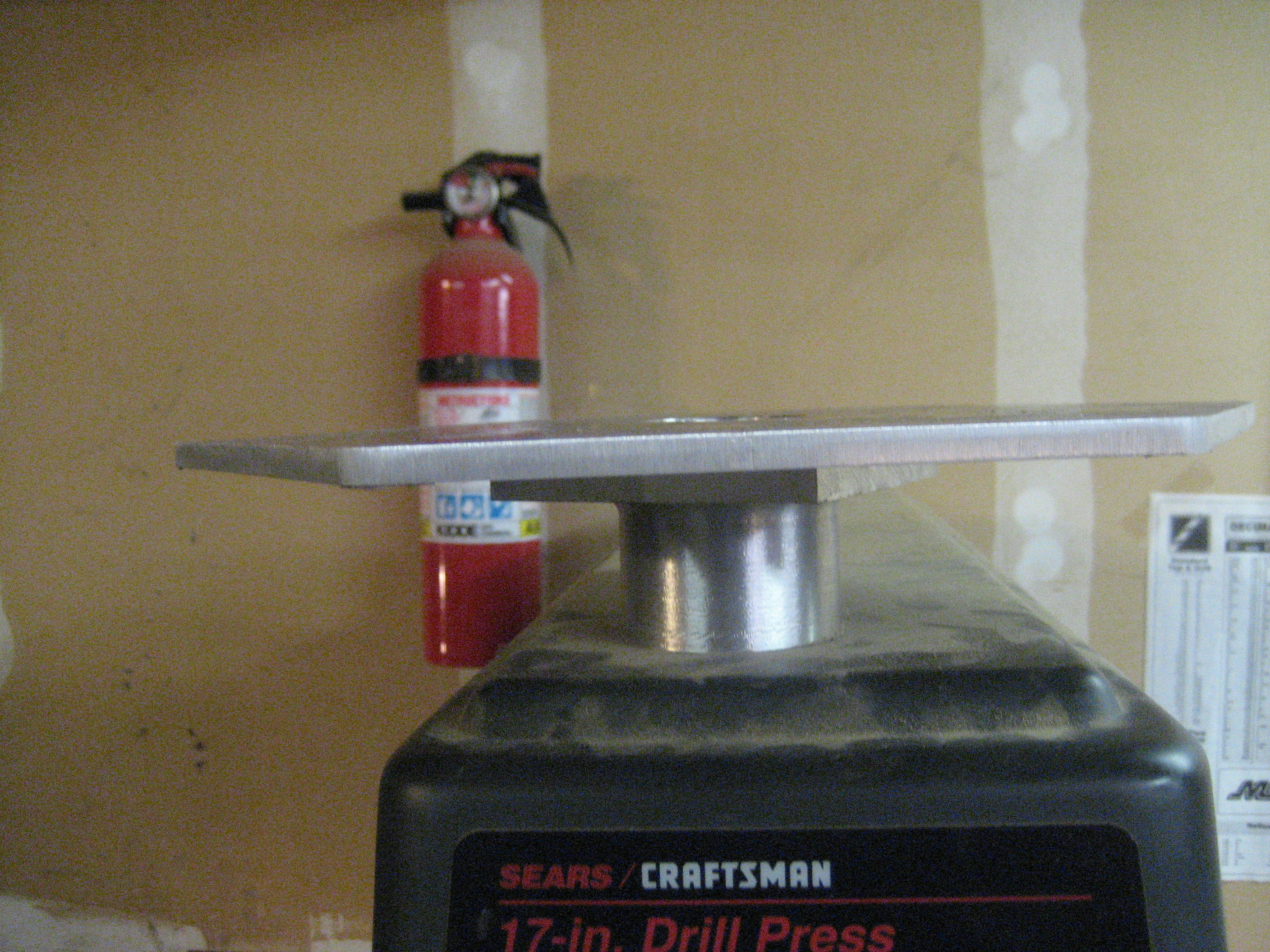
The base plate is 0.25 inch 2024-T3 aluminum. Sides are about 5.75 inches. 6061-T6 would be suitable as well, but I happened to have this piece in my metal stock.
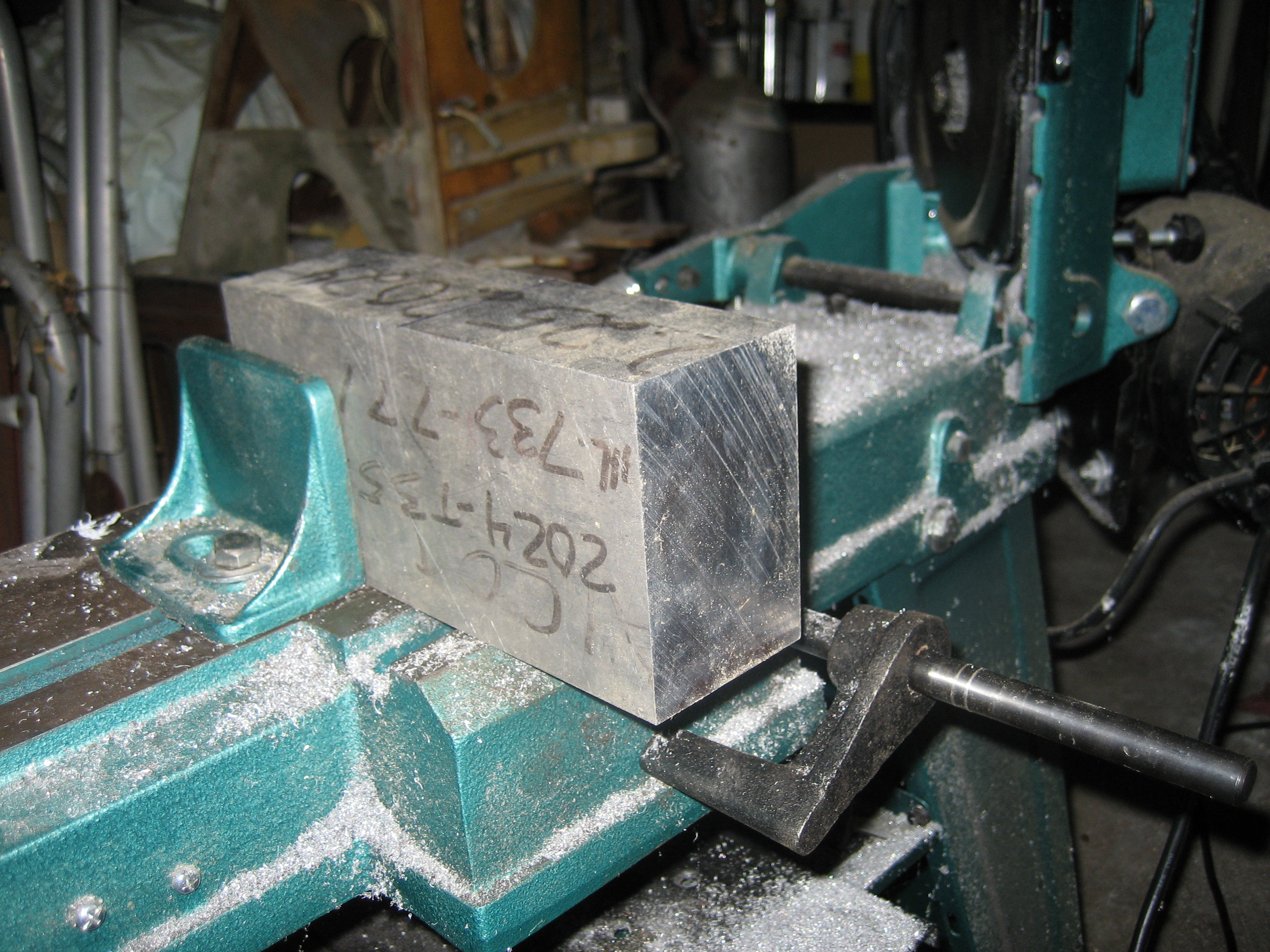
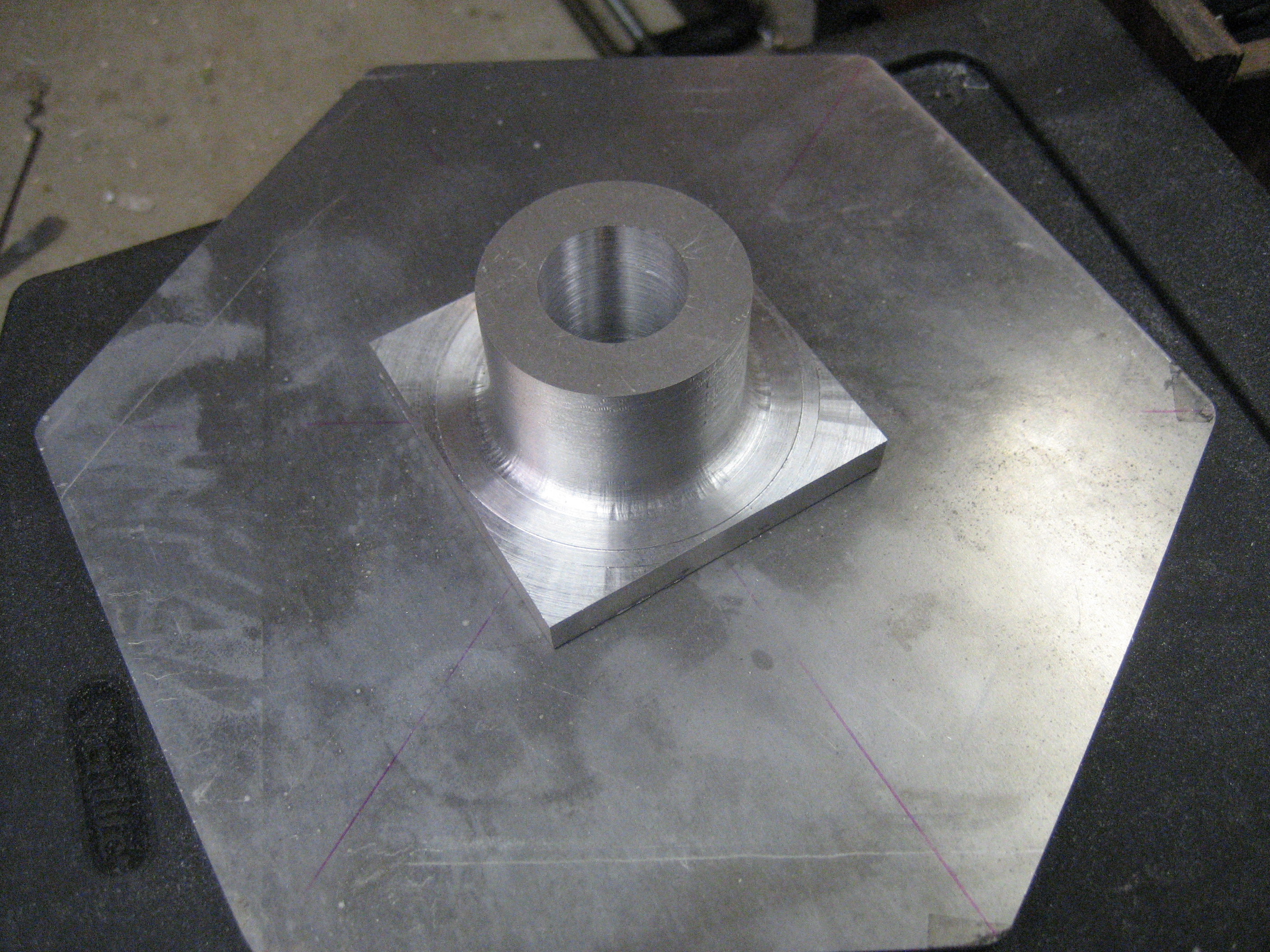
Most homemade hex beams use two fencing floor flanges for the hub. I decided to roll my own out of a block of 2024 aluminum.
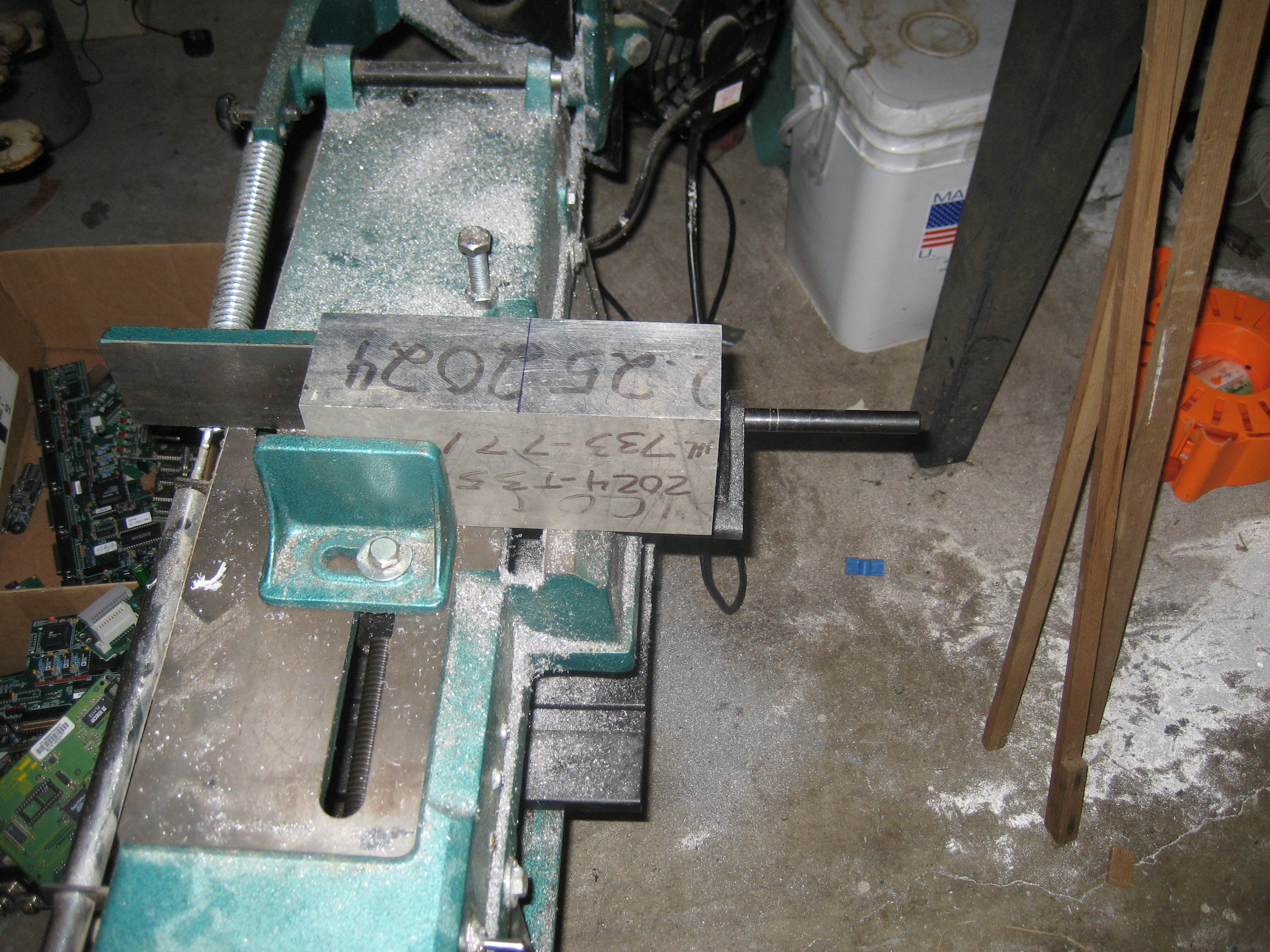
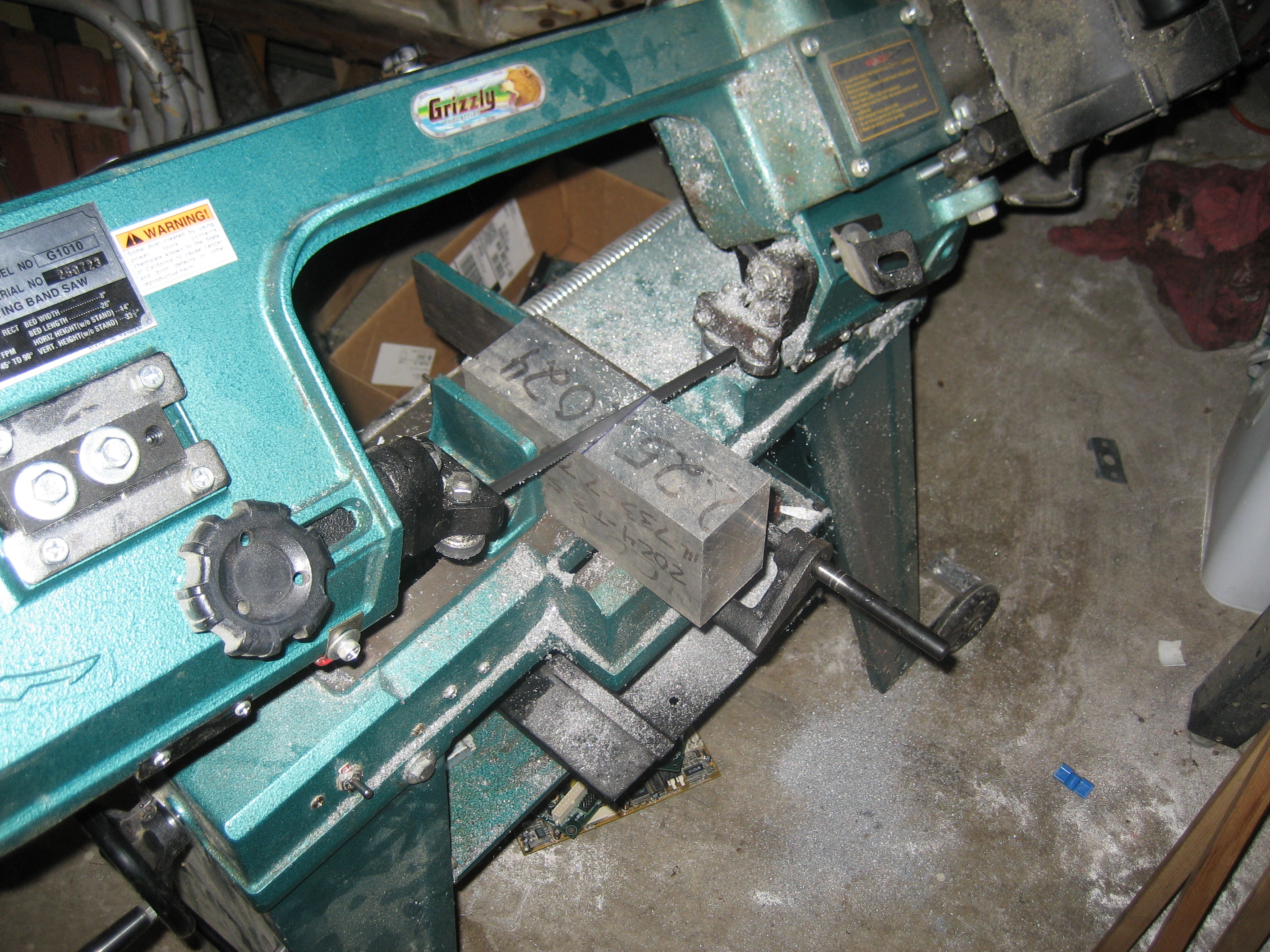
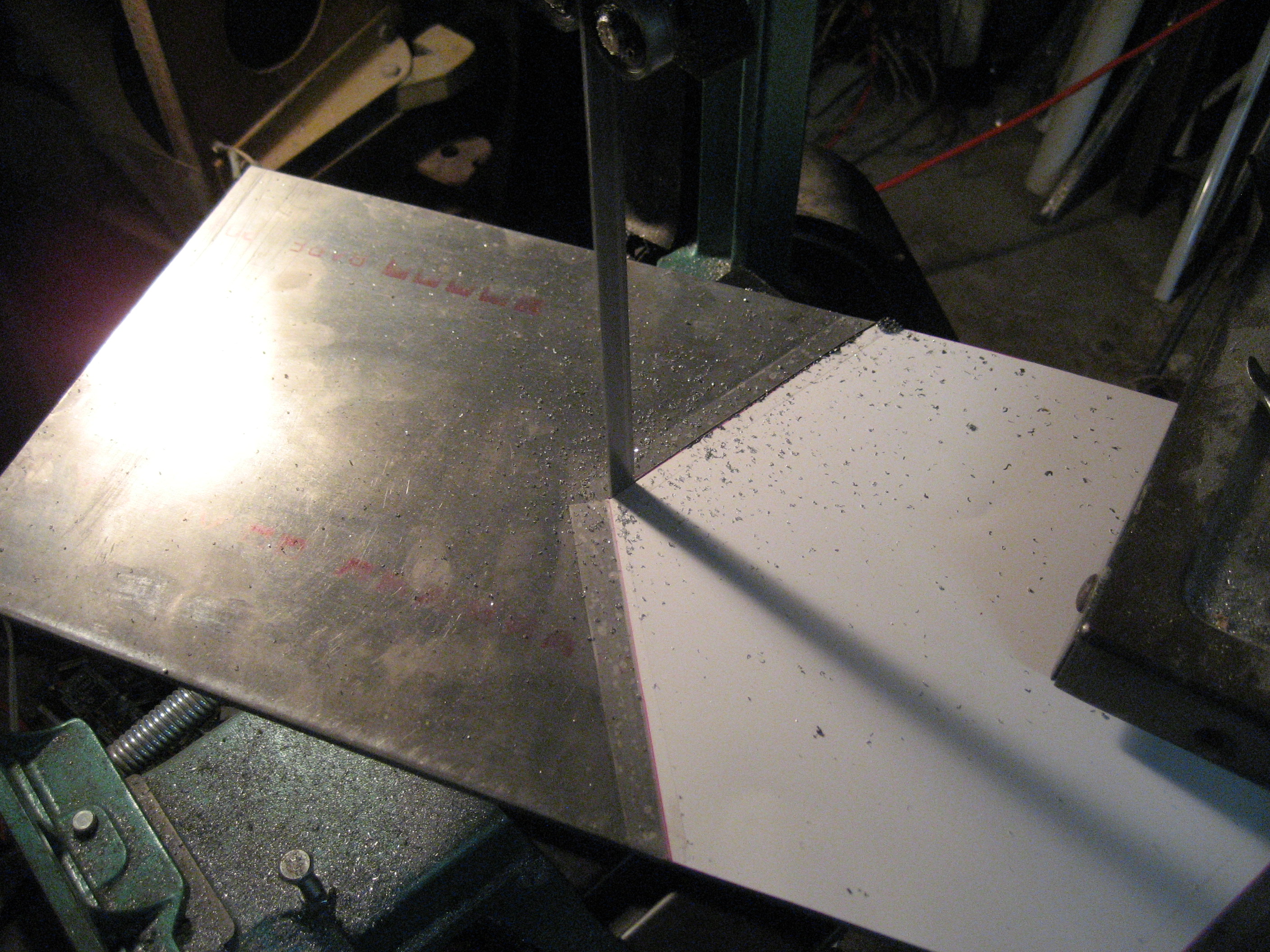
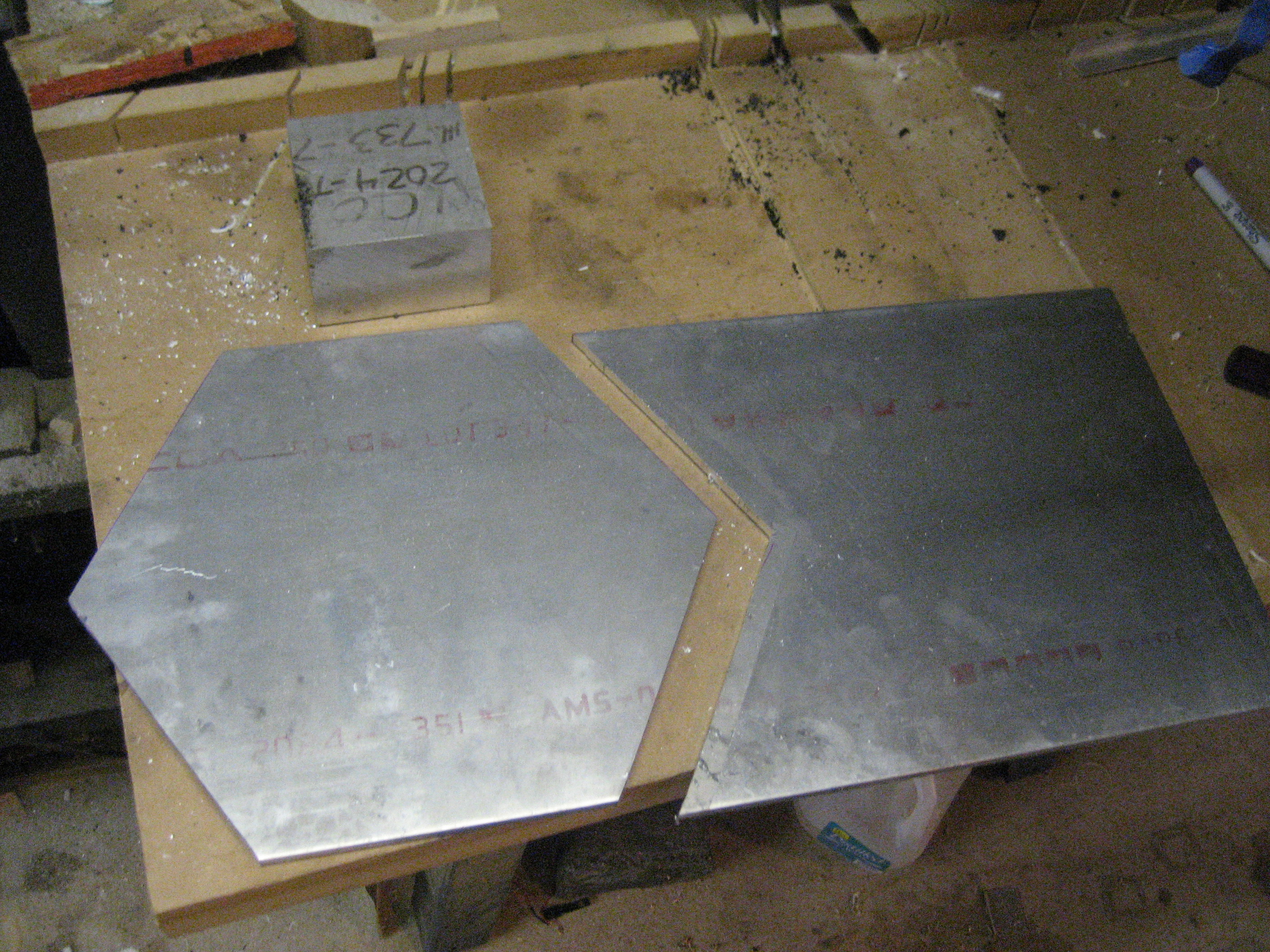
Here are the raw parts for the base plate
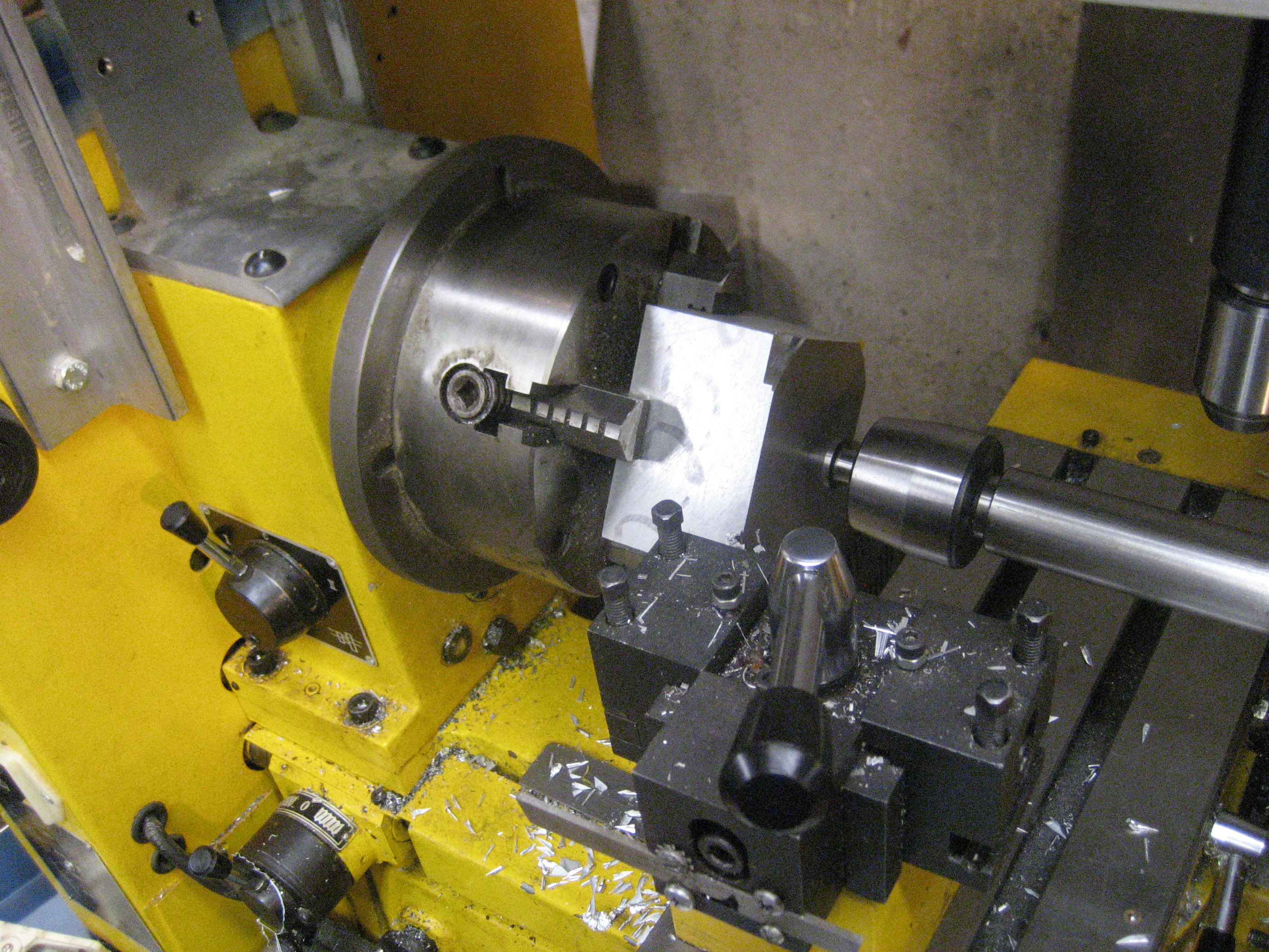
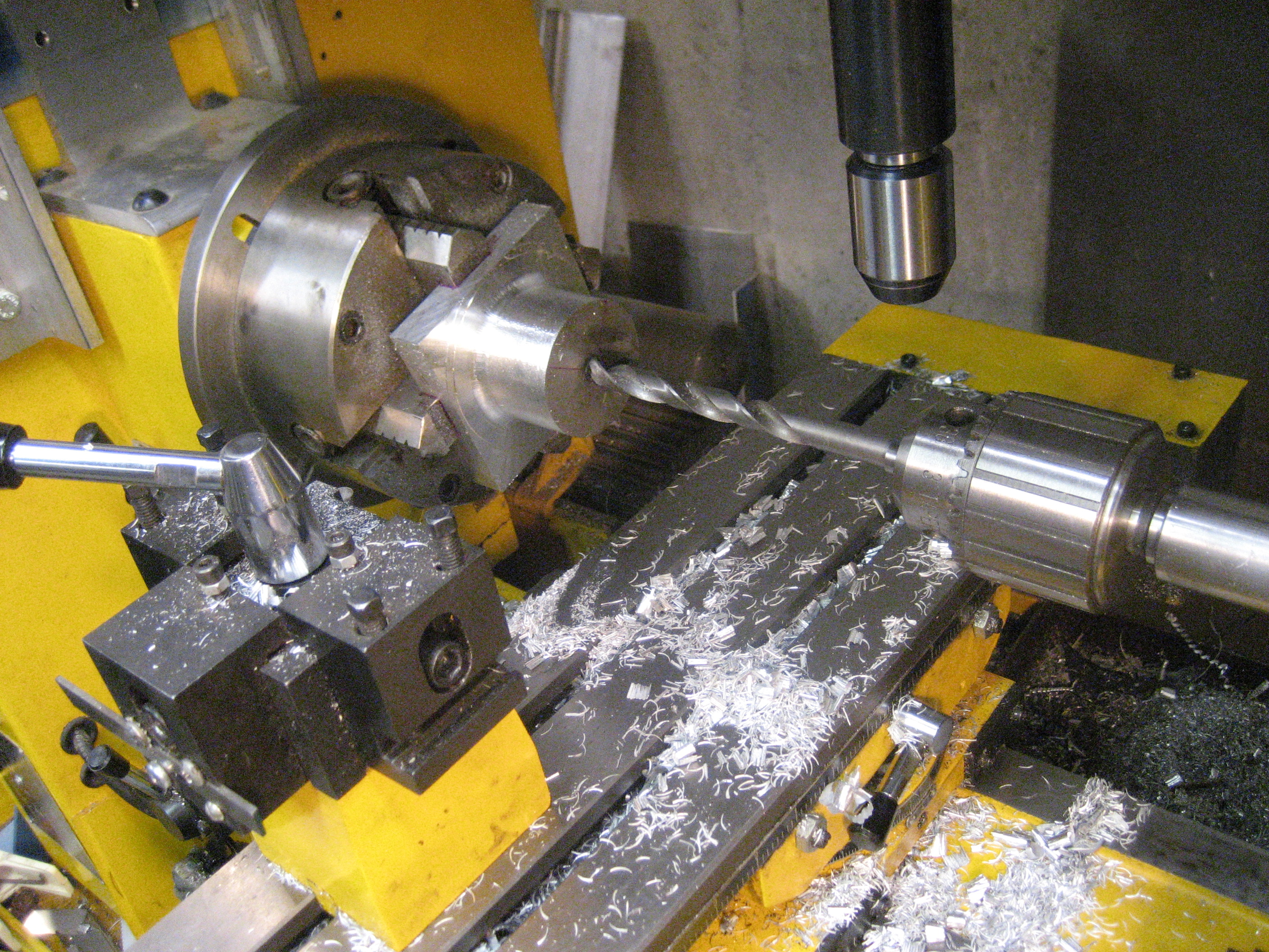
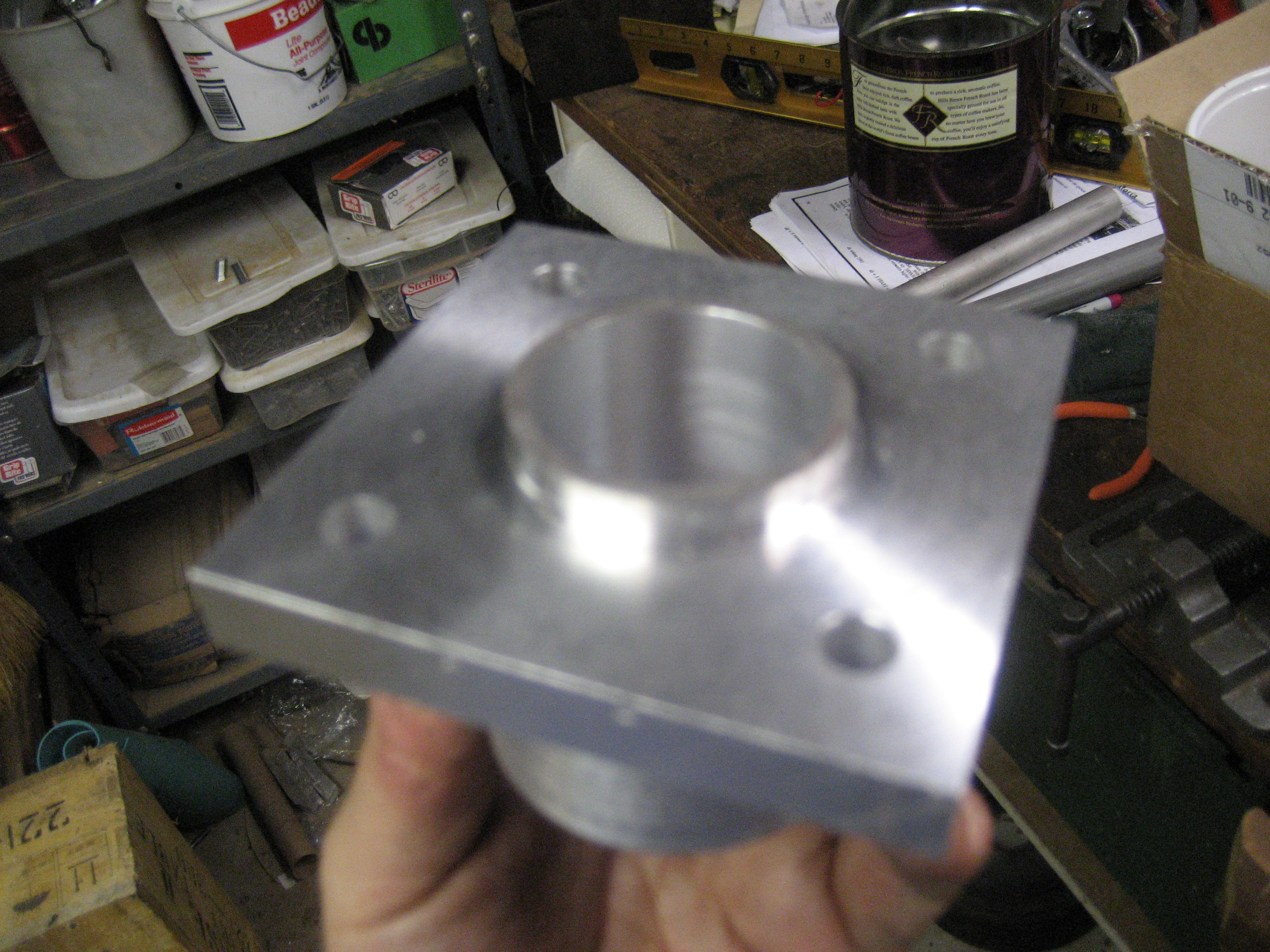
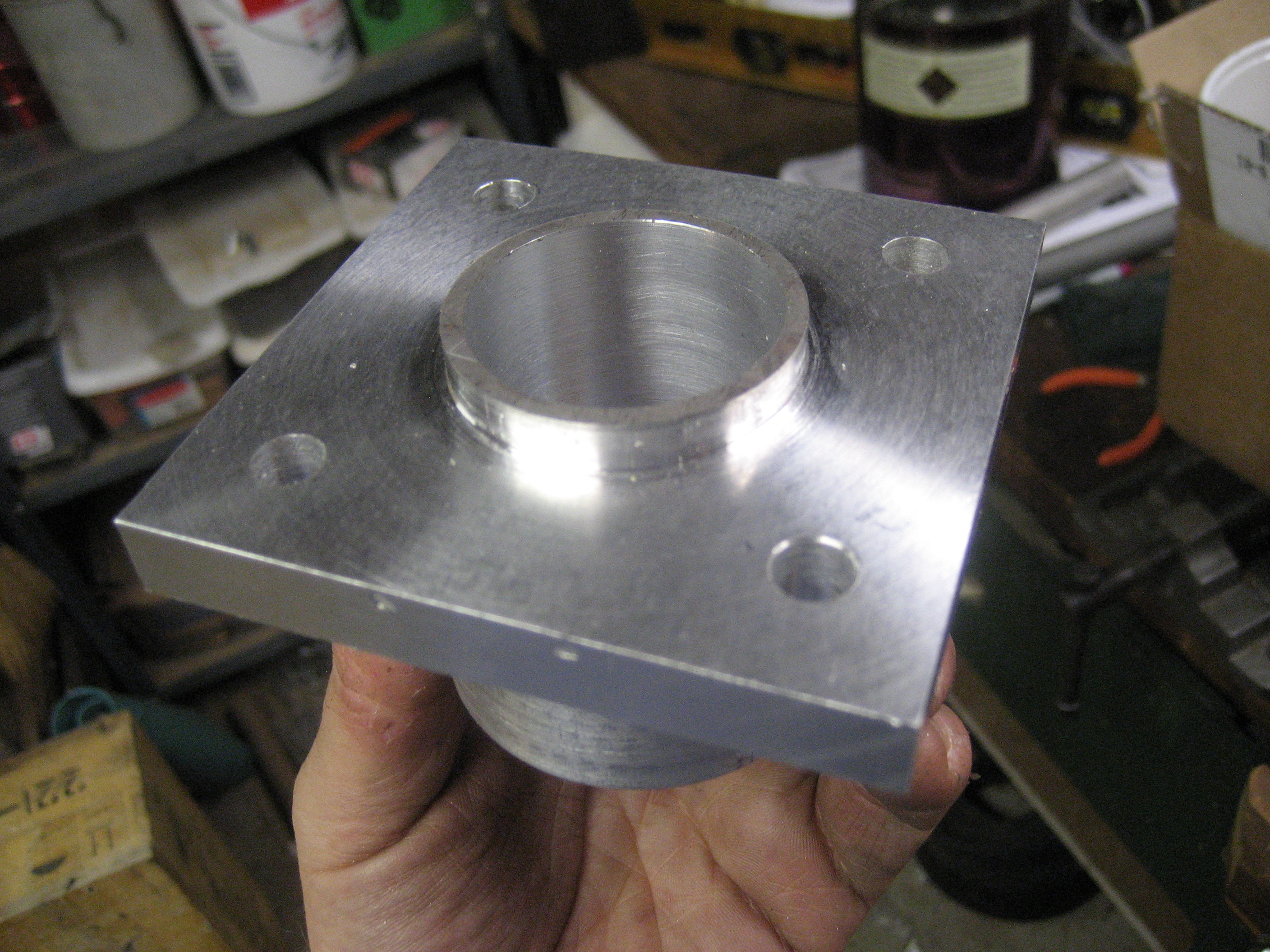
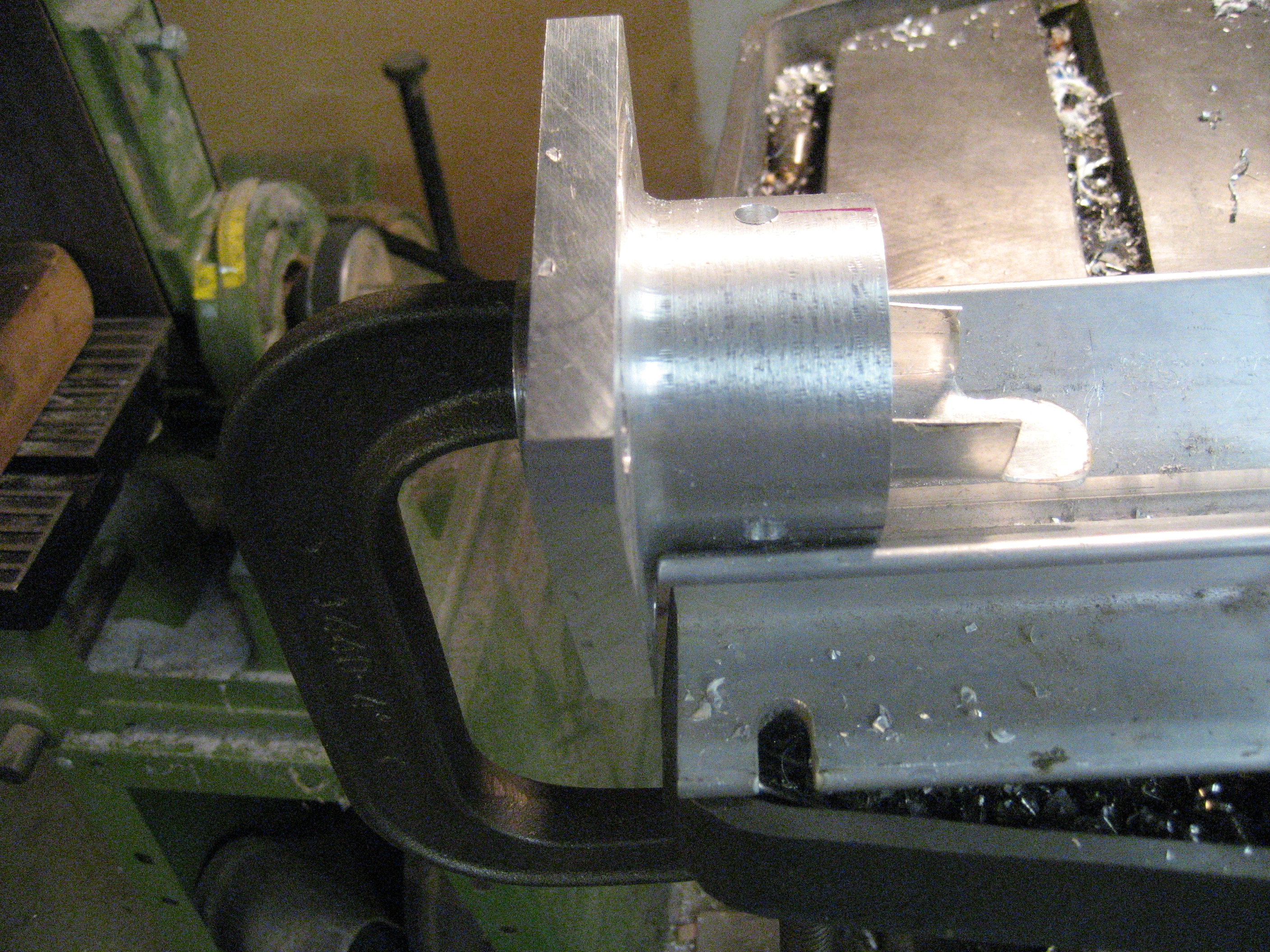
Hub machining underway.
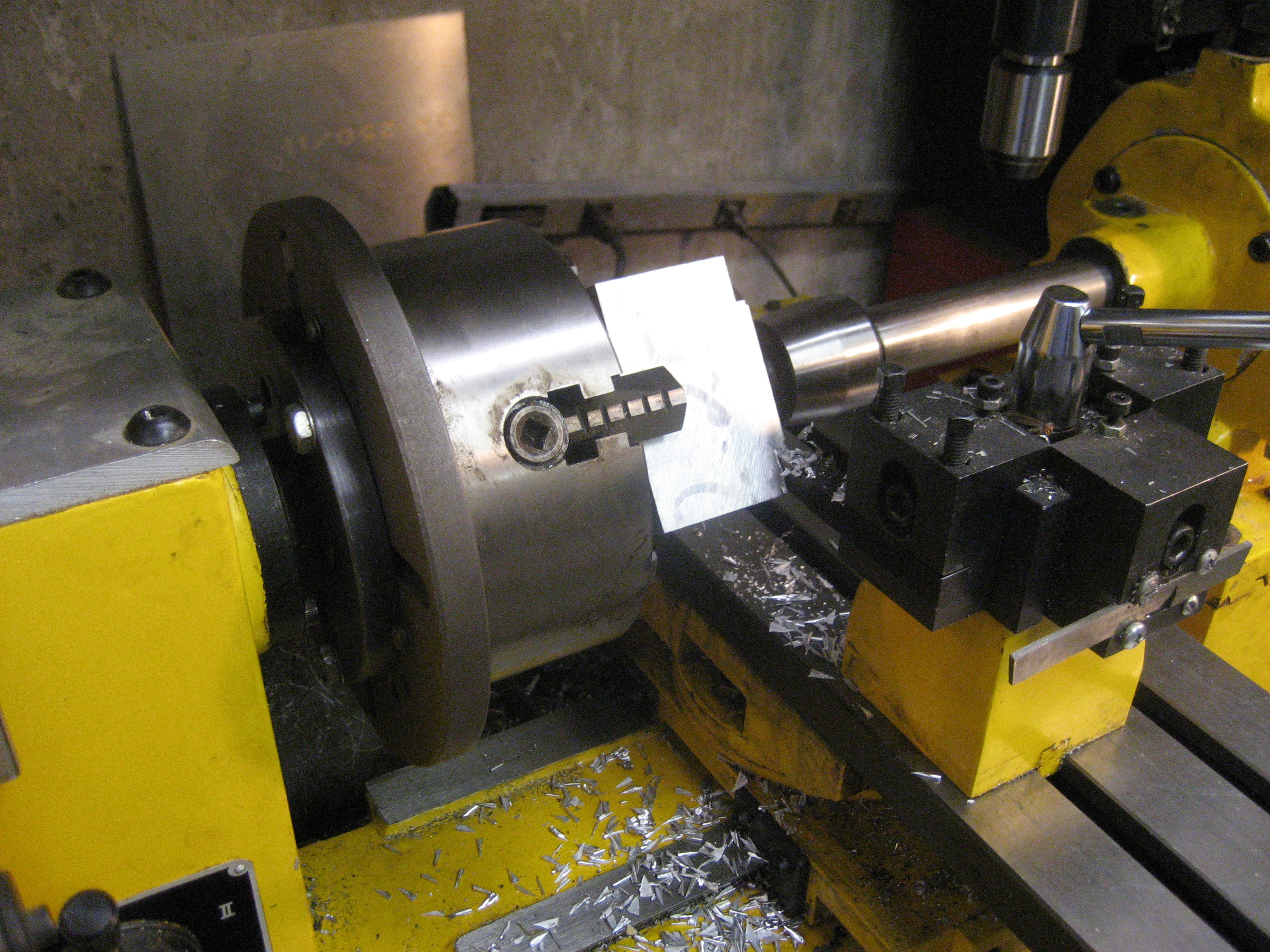
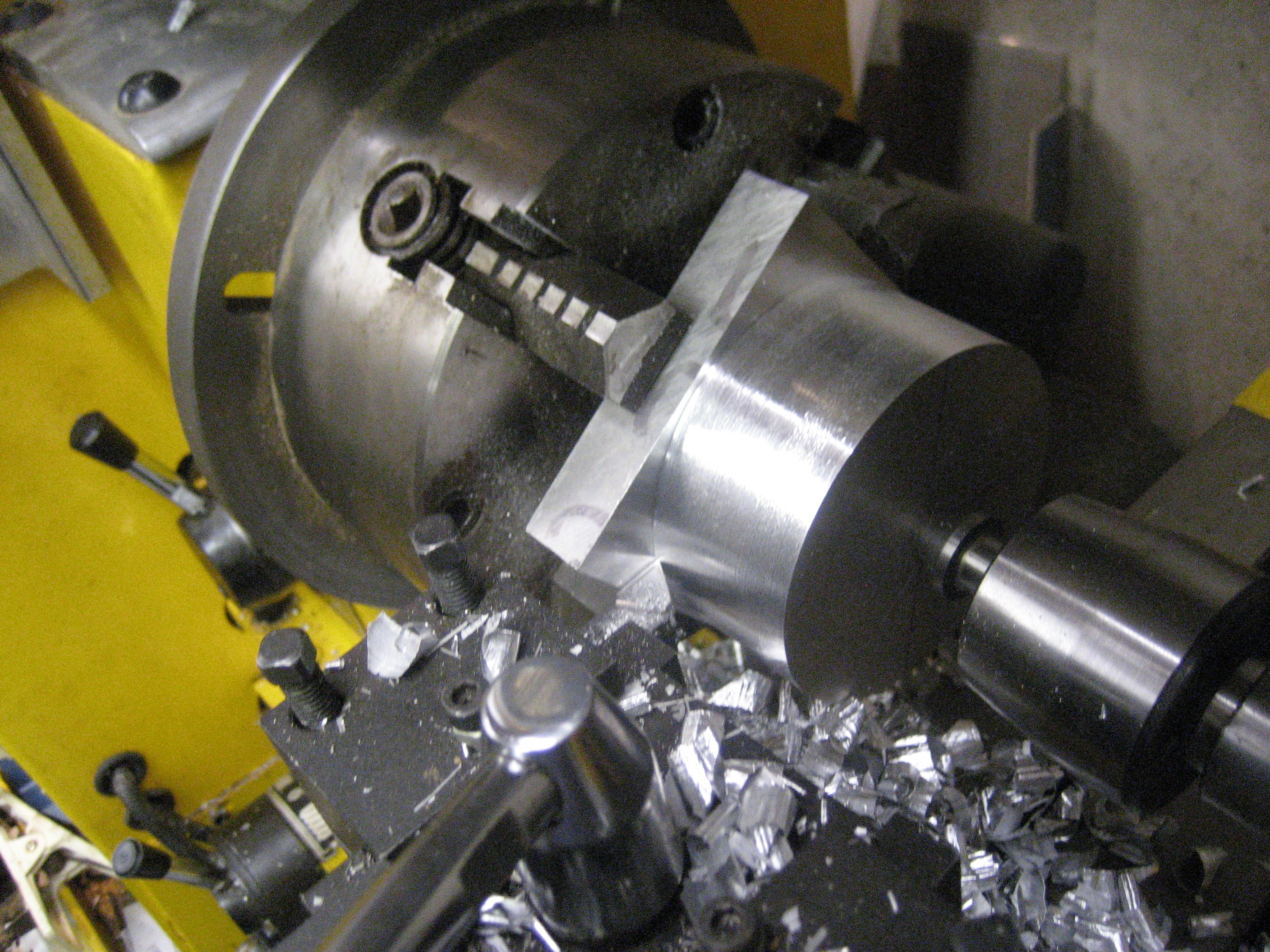
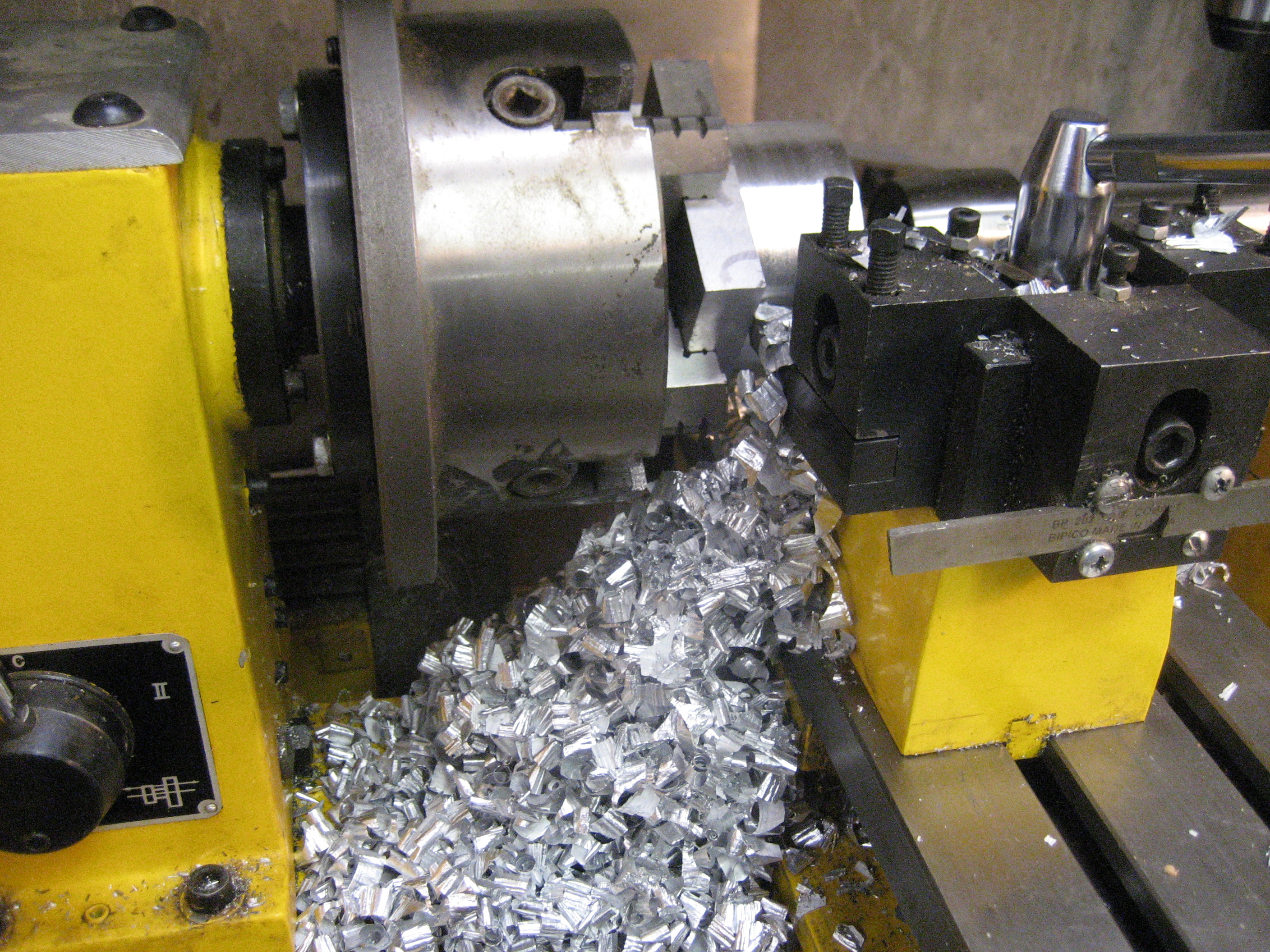
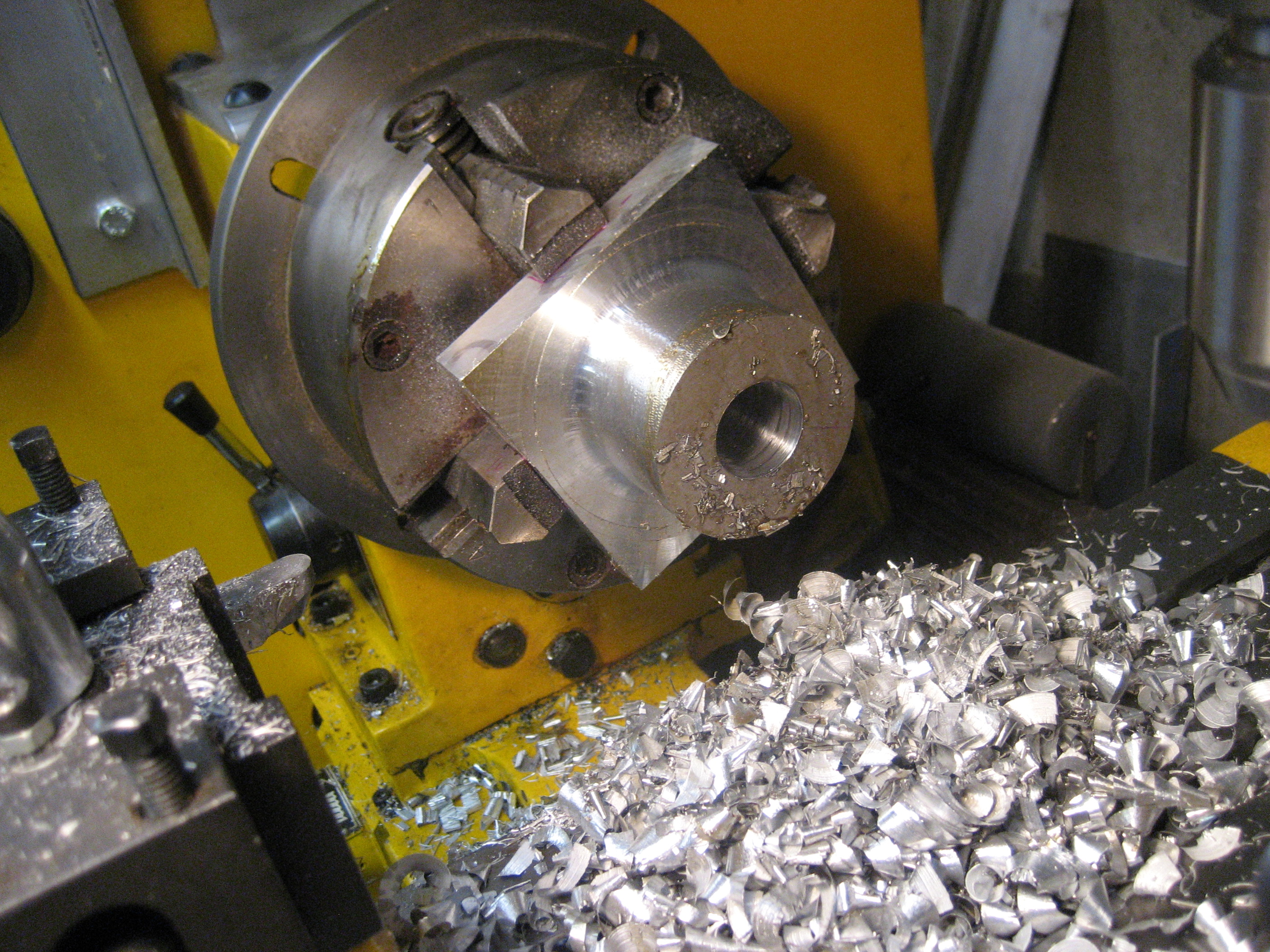
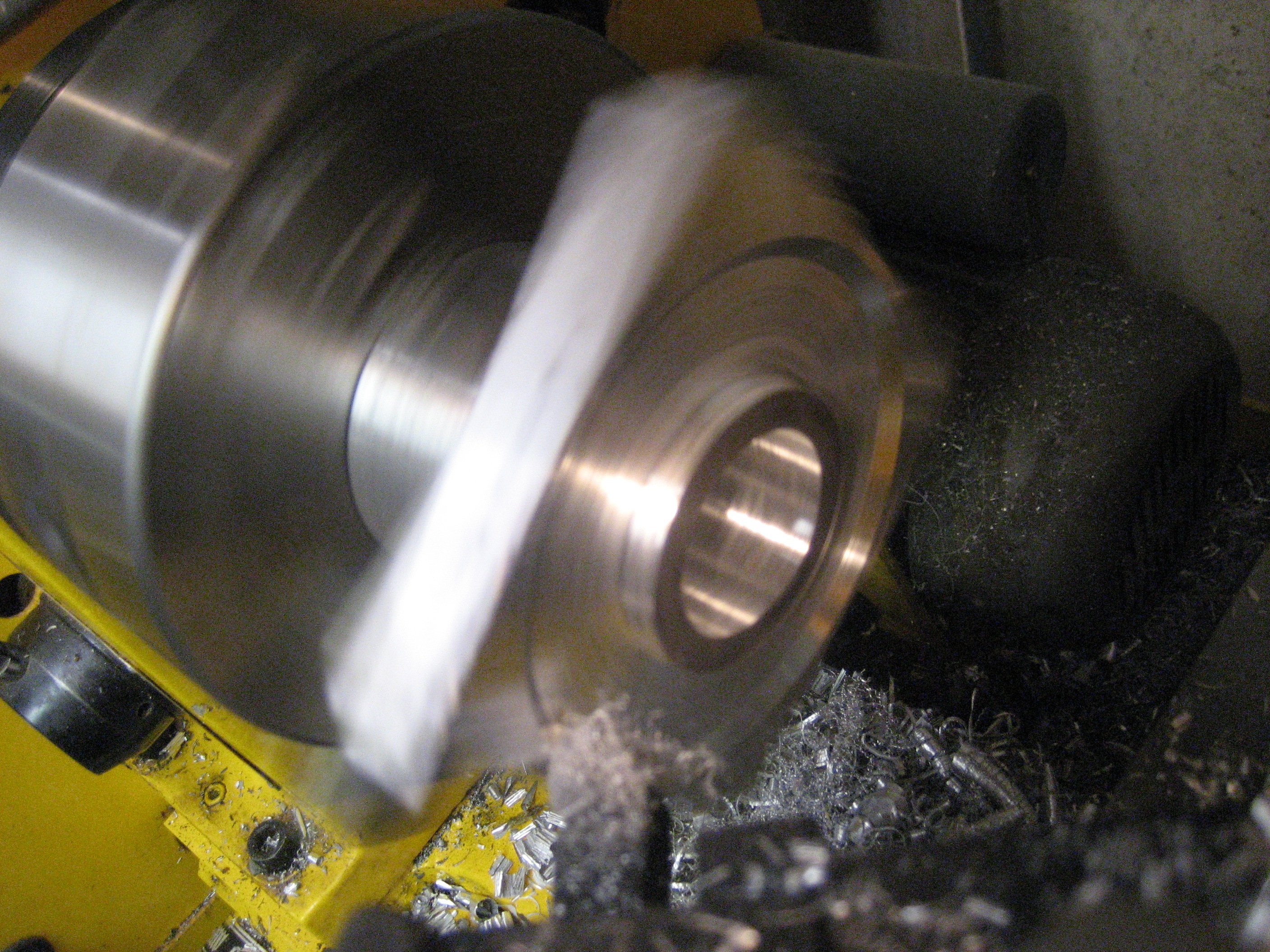
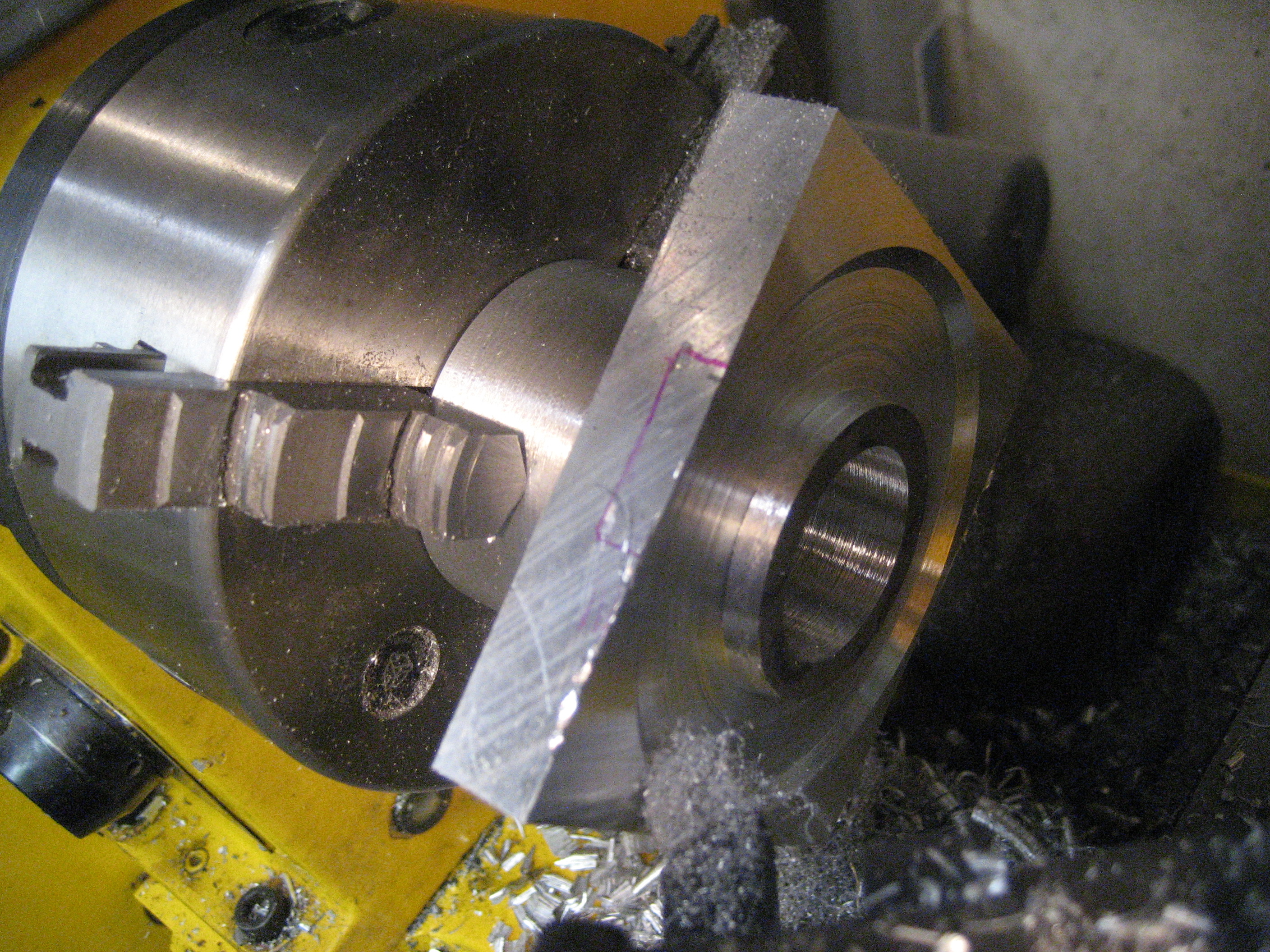
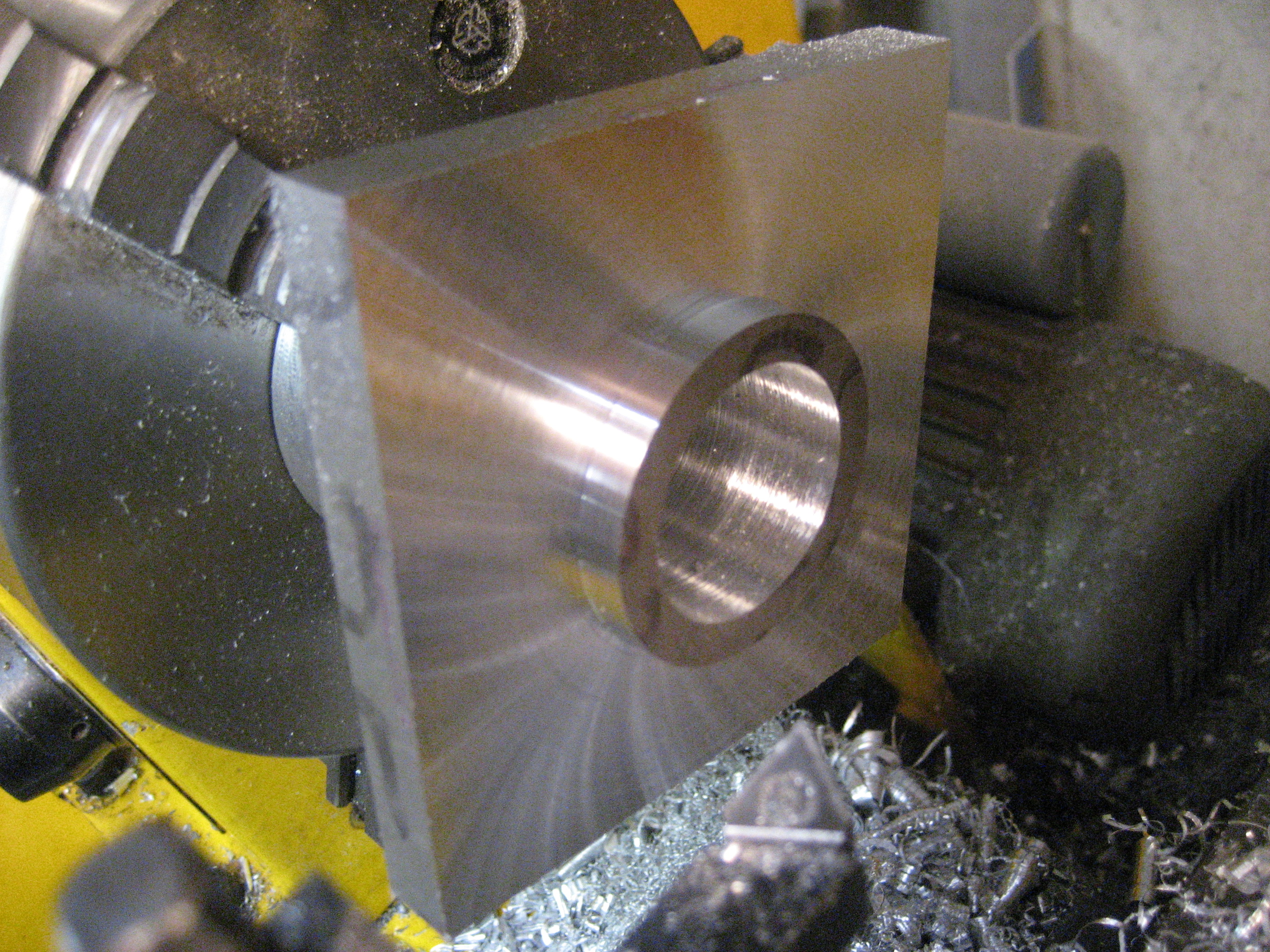
Ohhhhh...shiny!
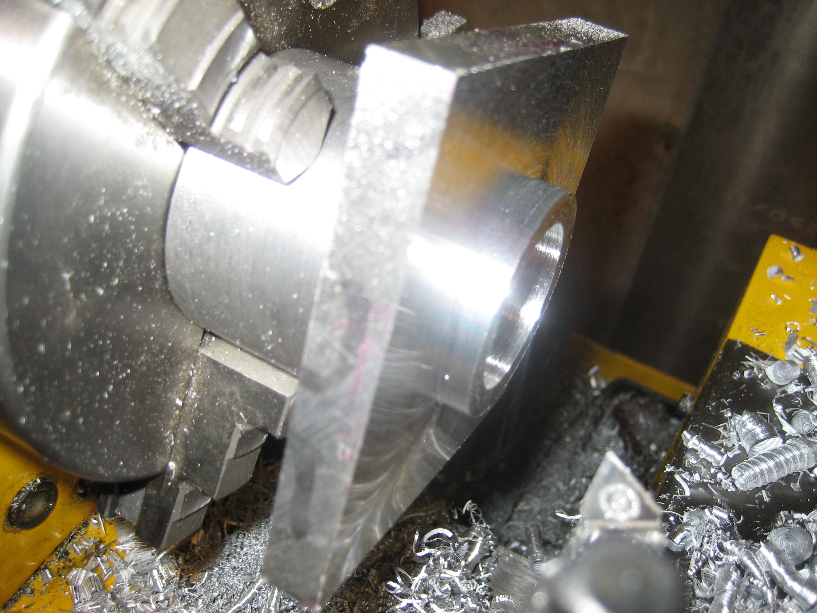
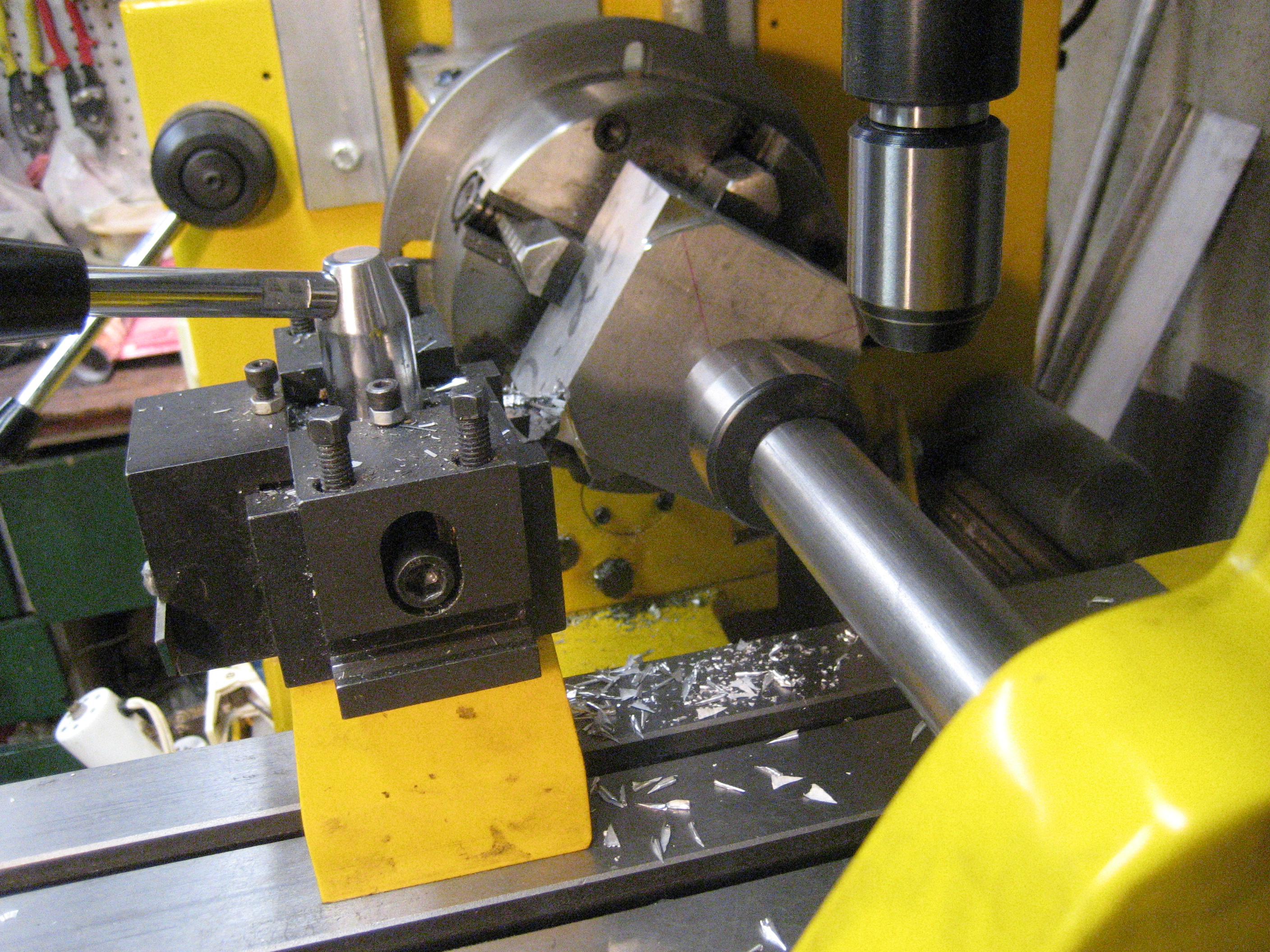
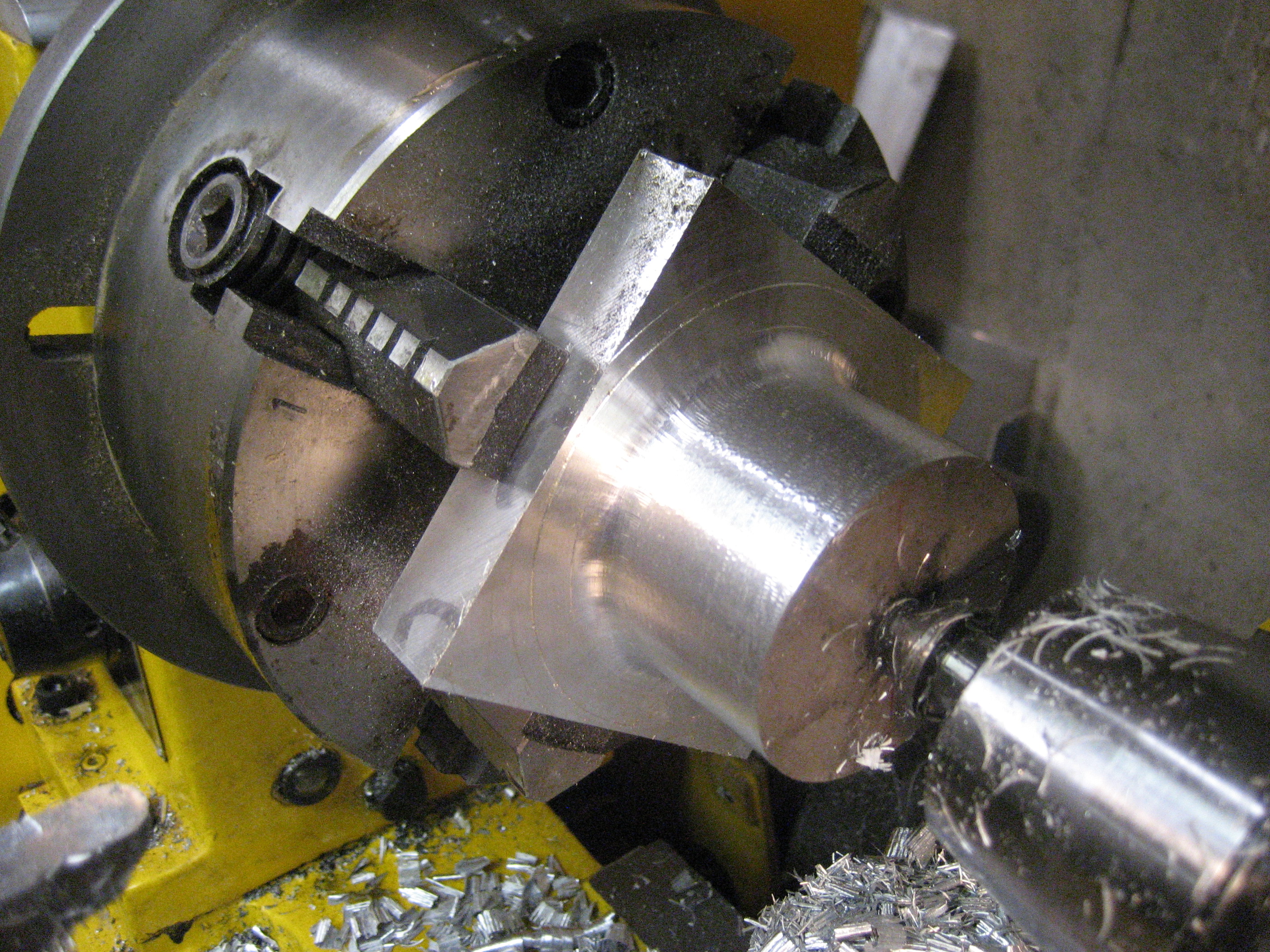
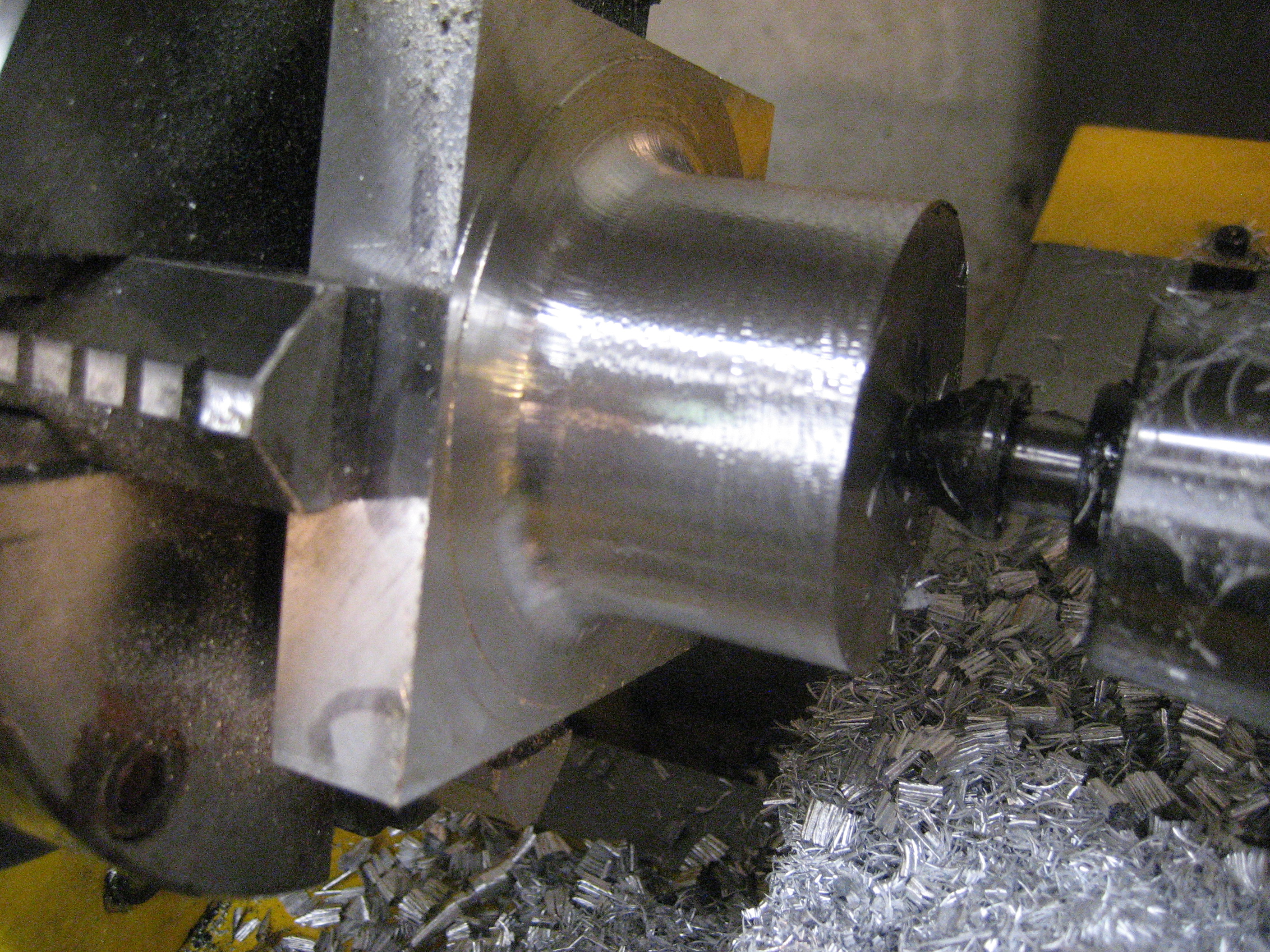
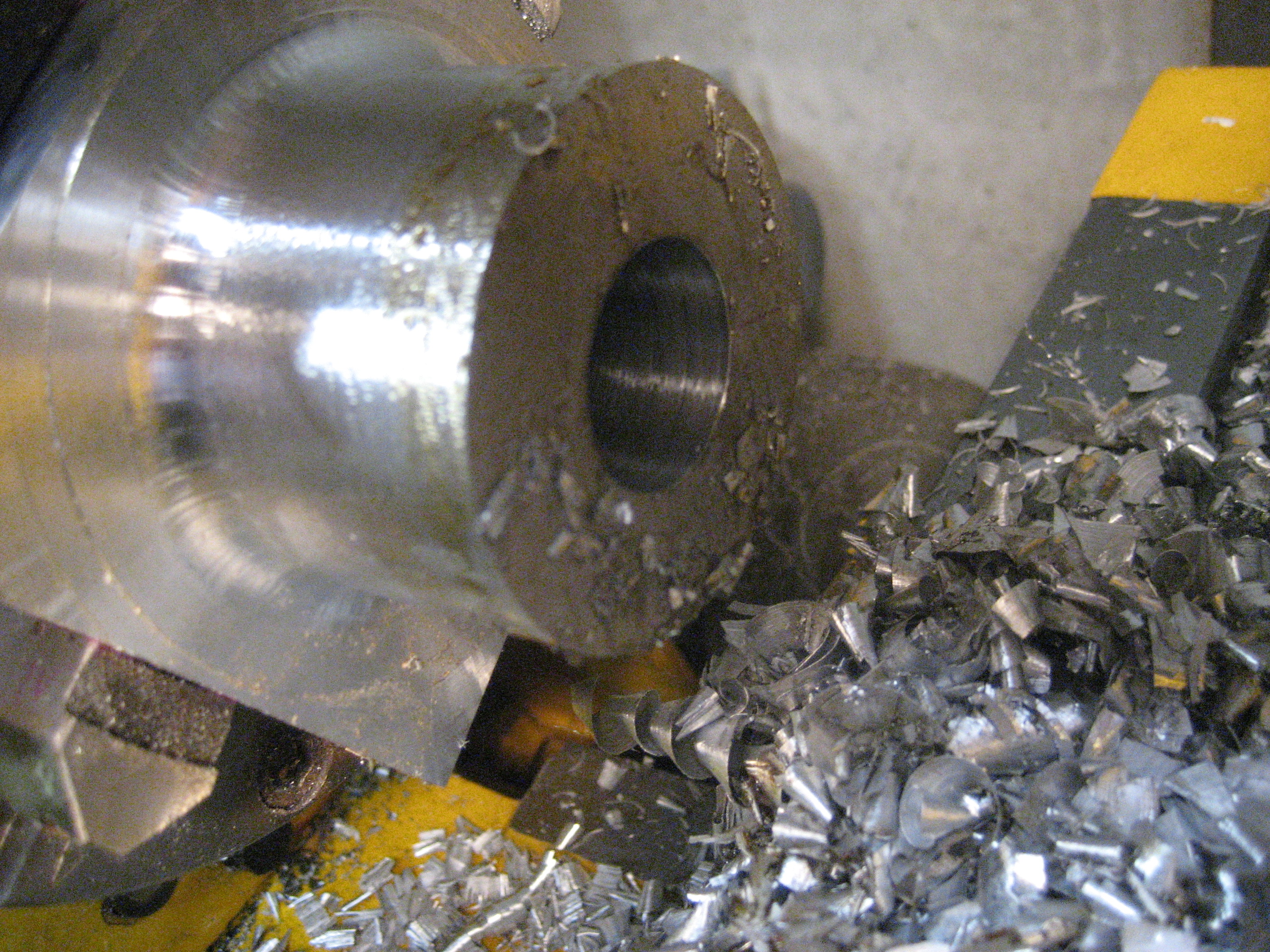
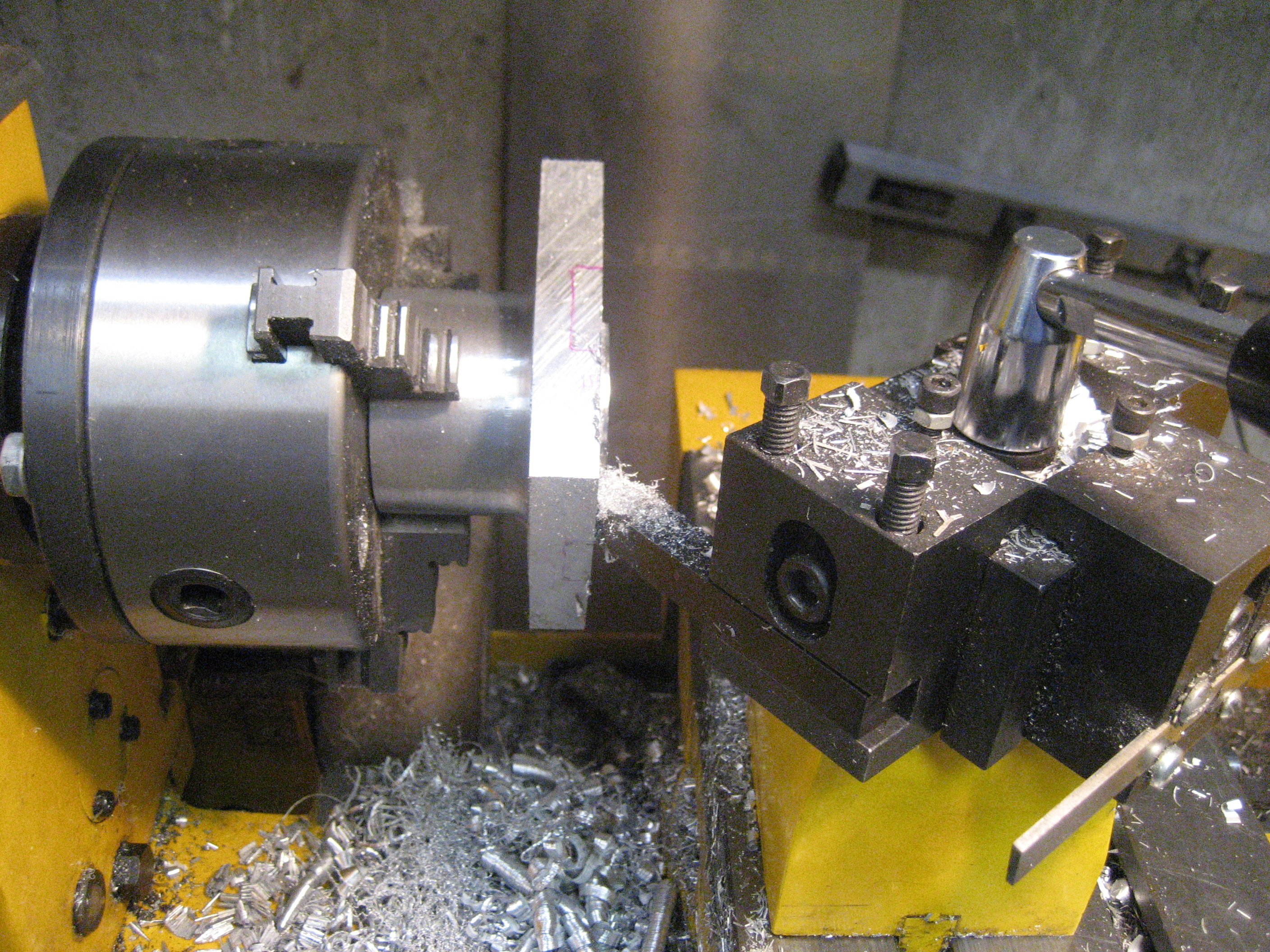
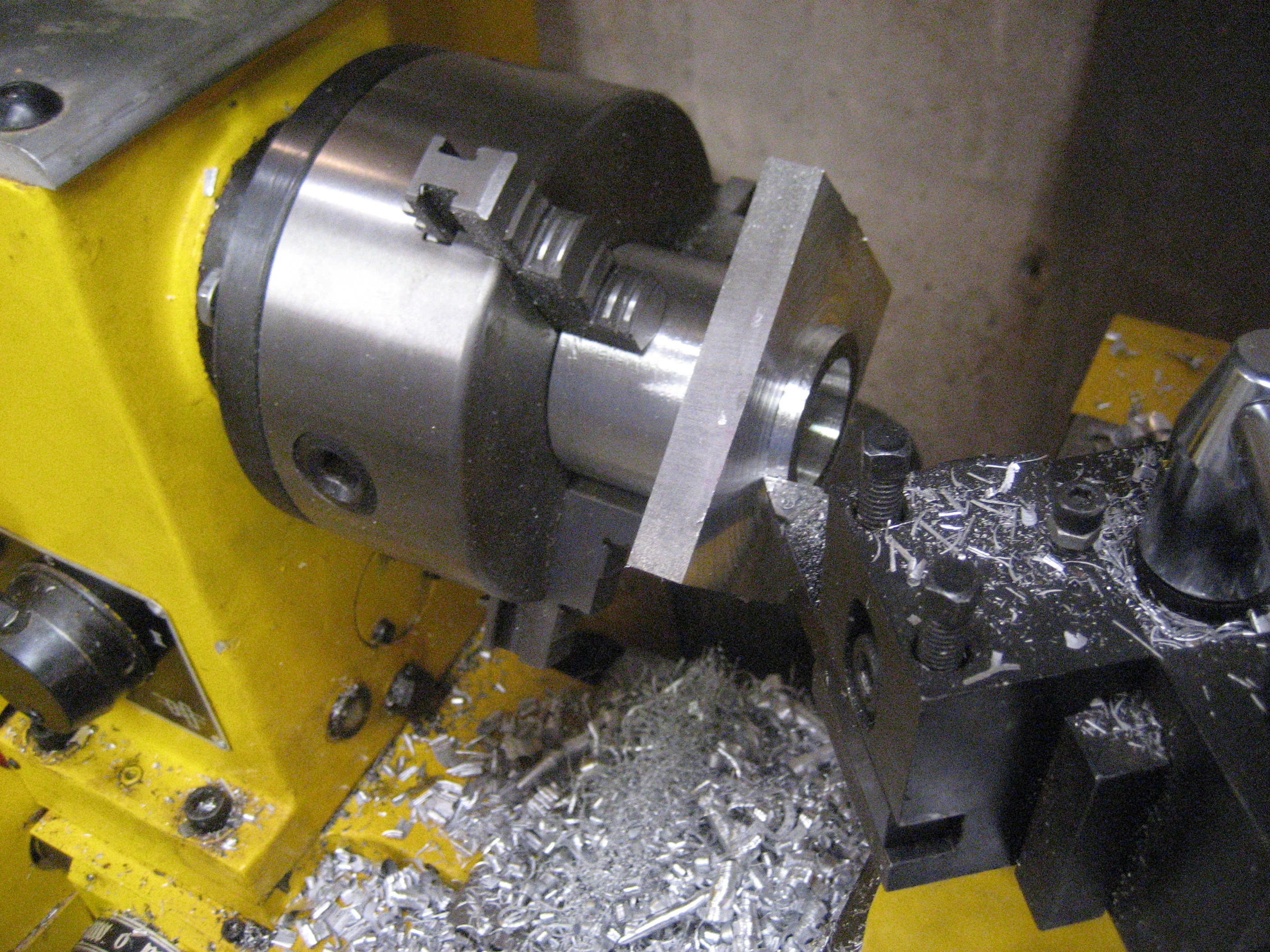
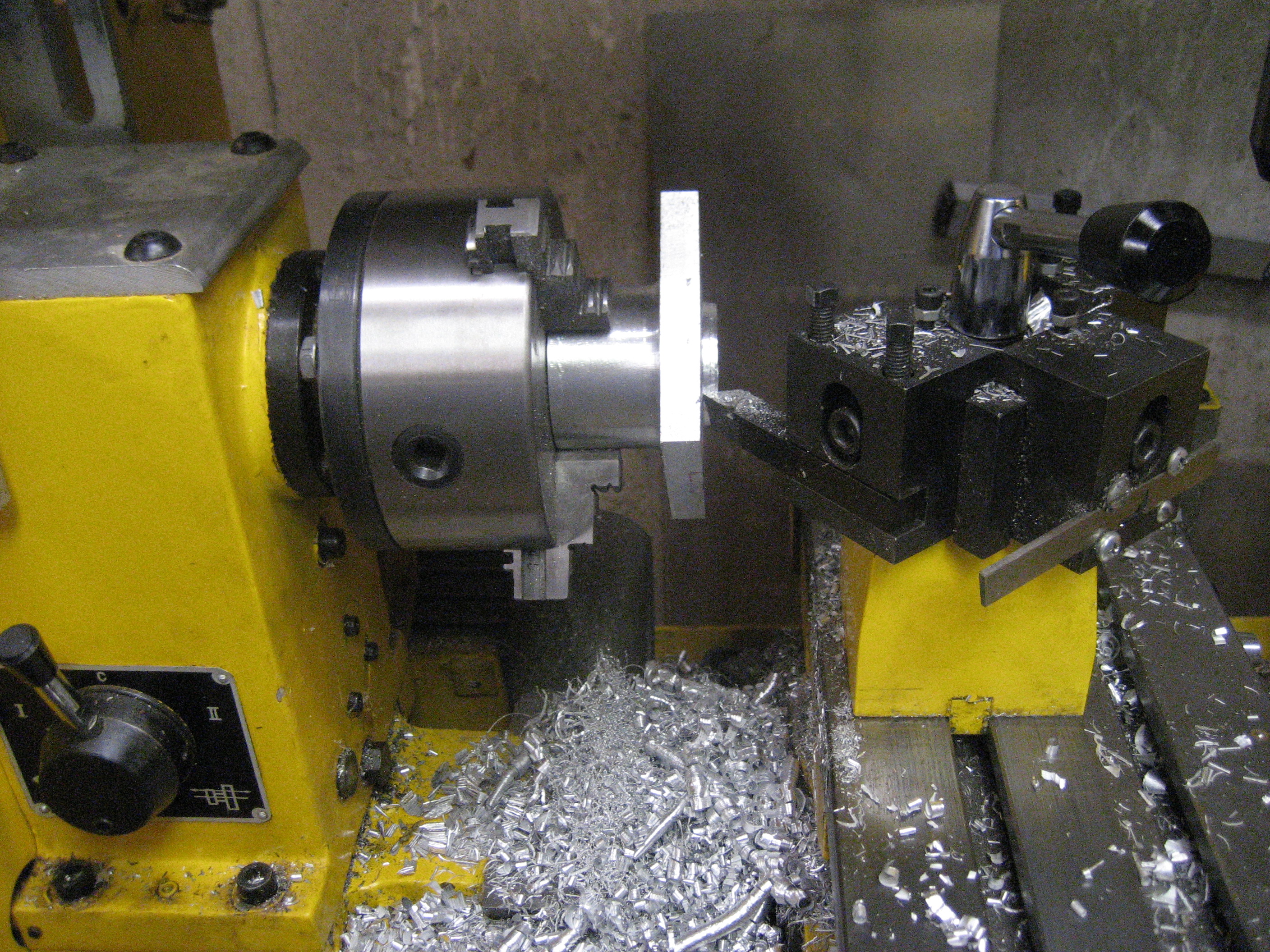
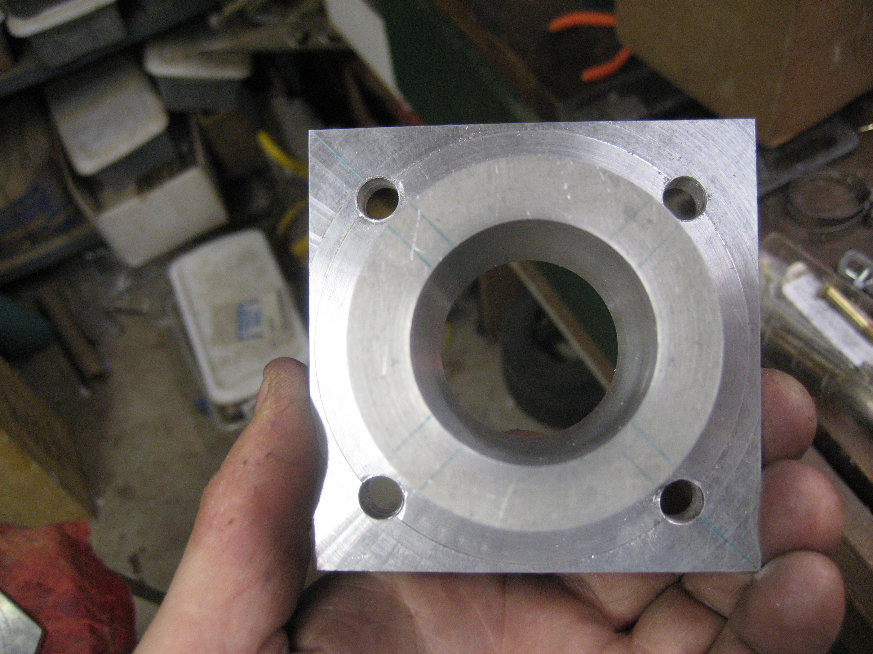
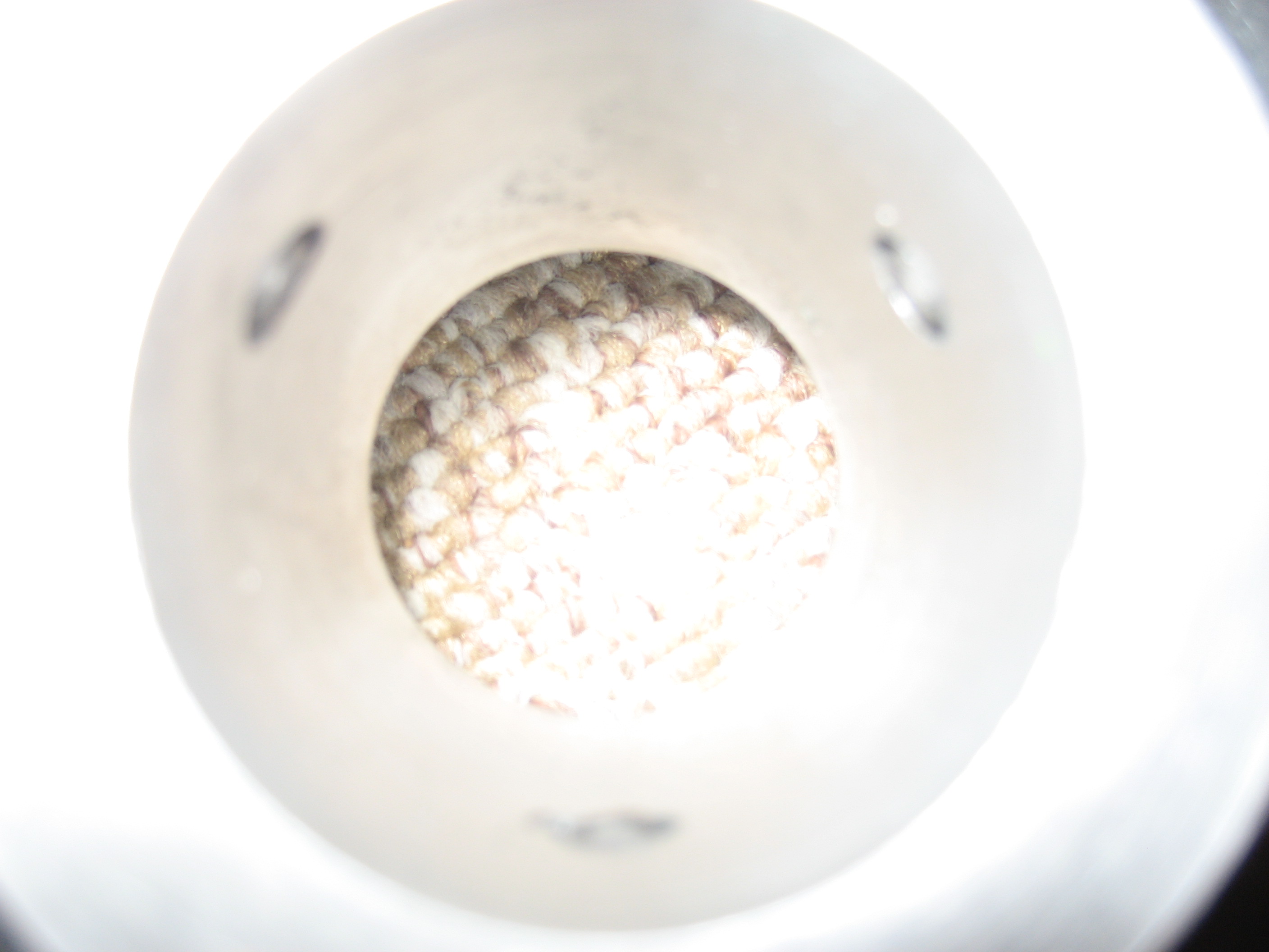
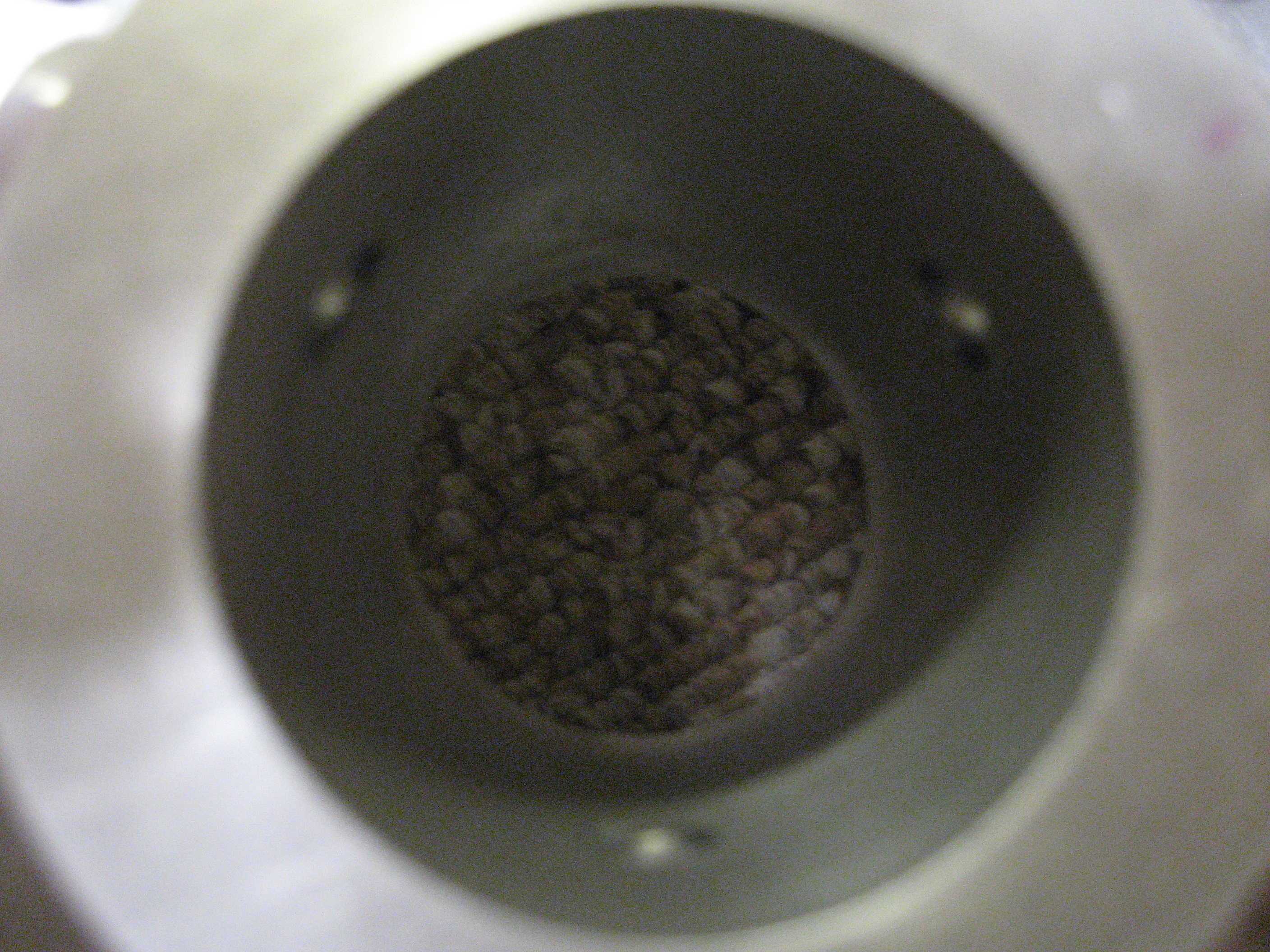
I used a fly-cutter for the center hole. These things make me nervous. I never quite trust that the hole will be of the desired size...
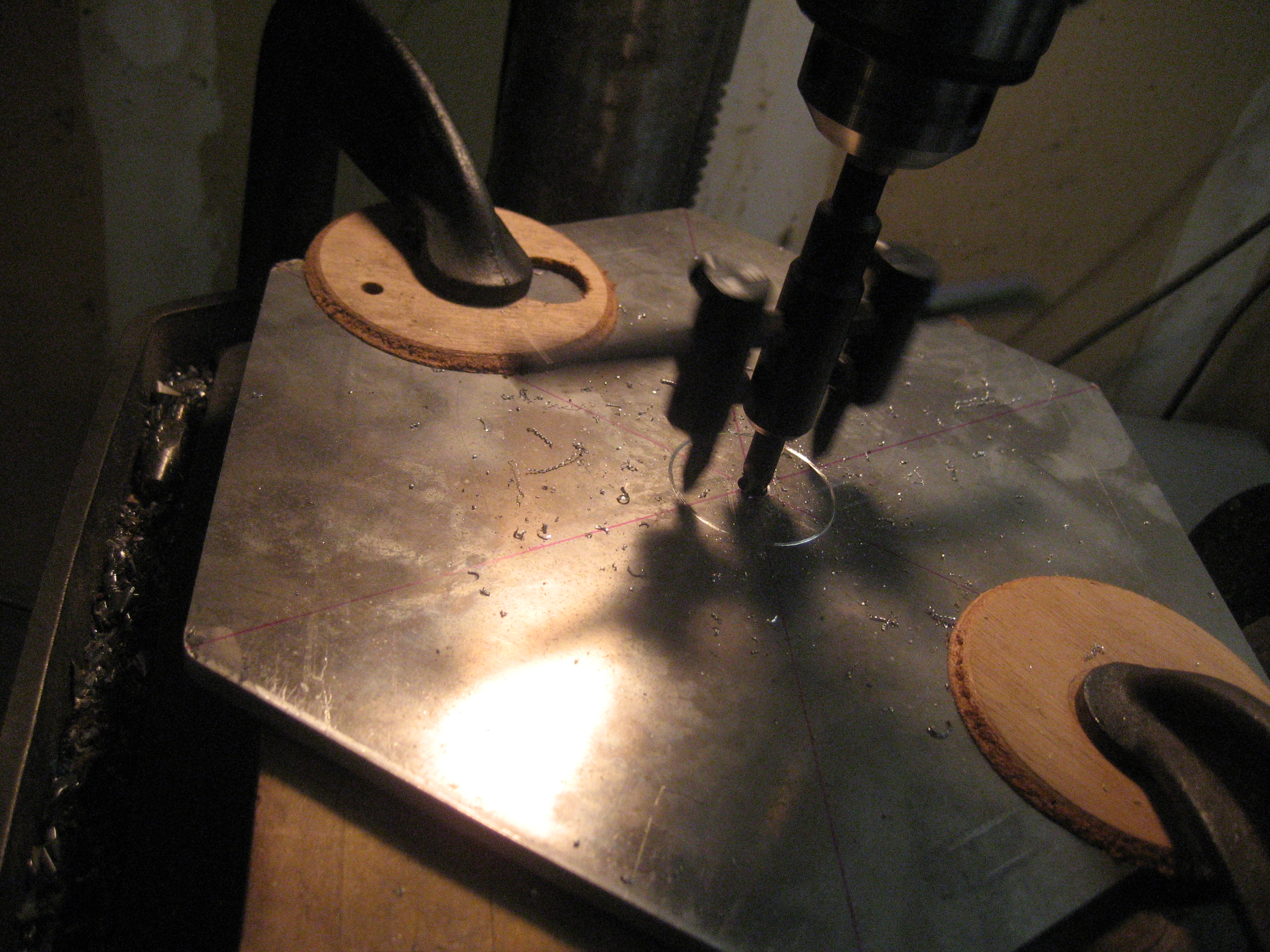
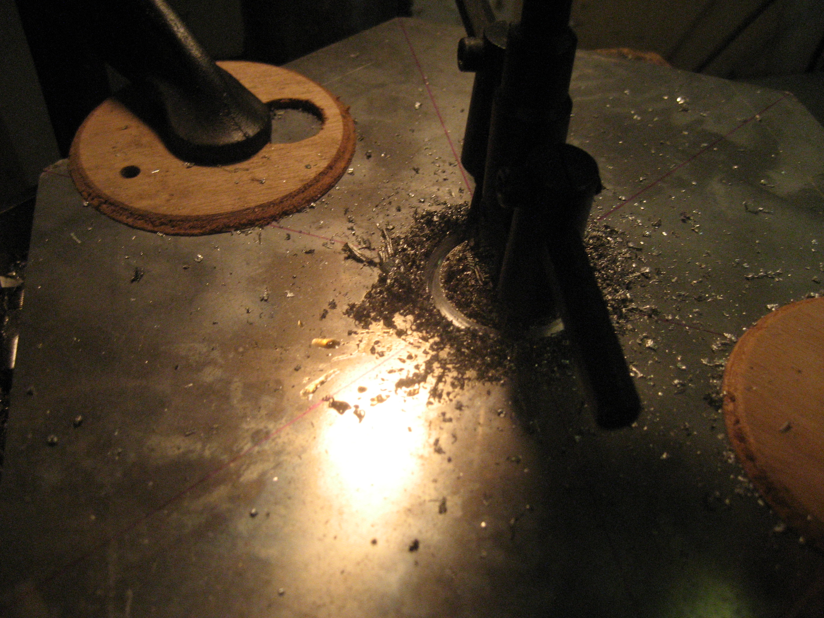

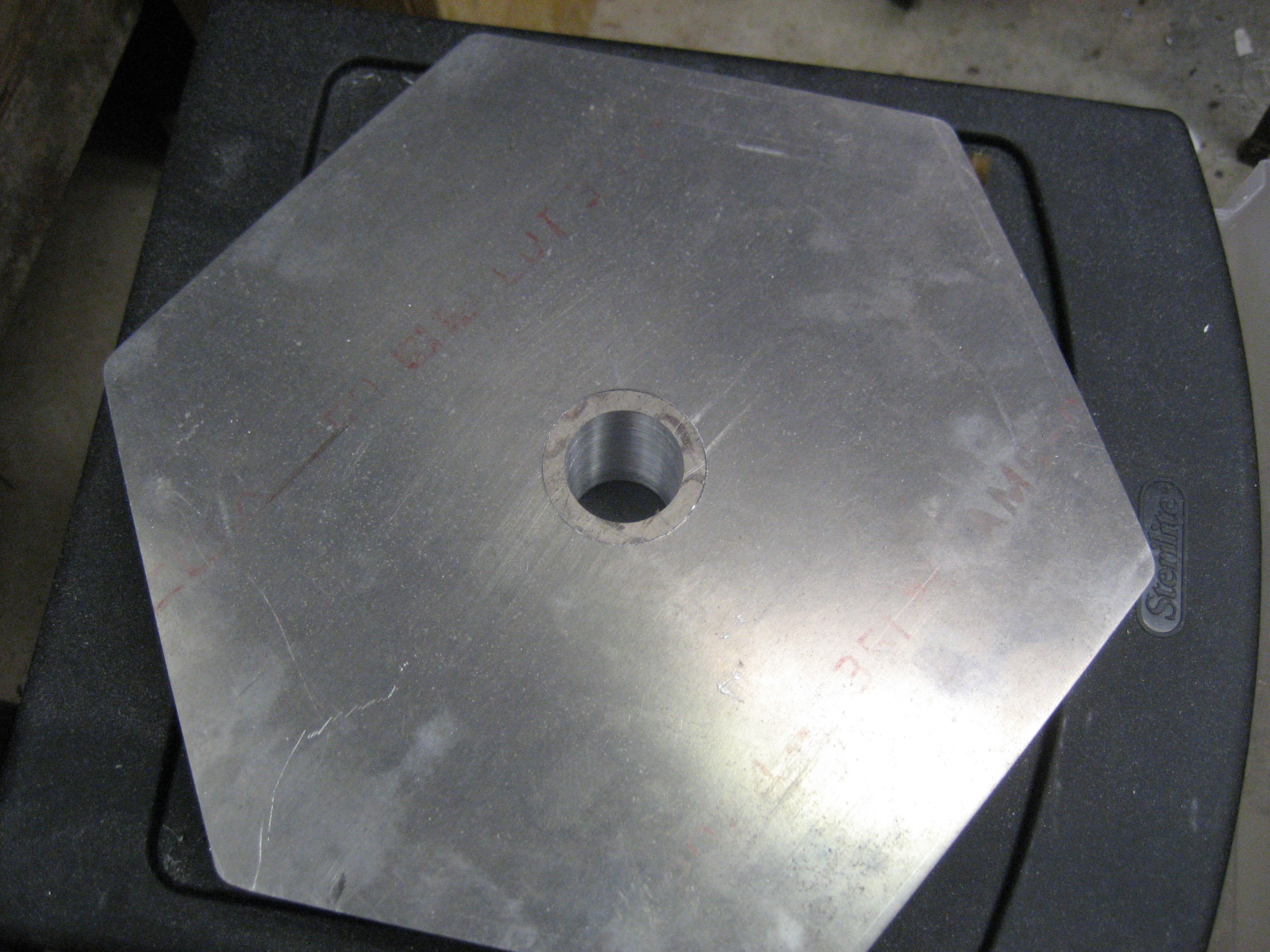
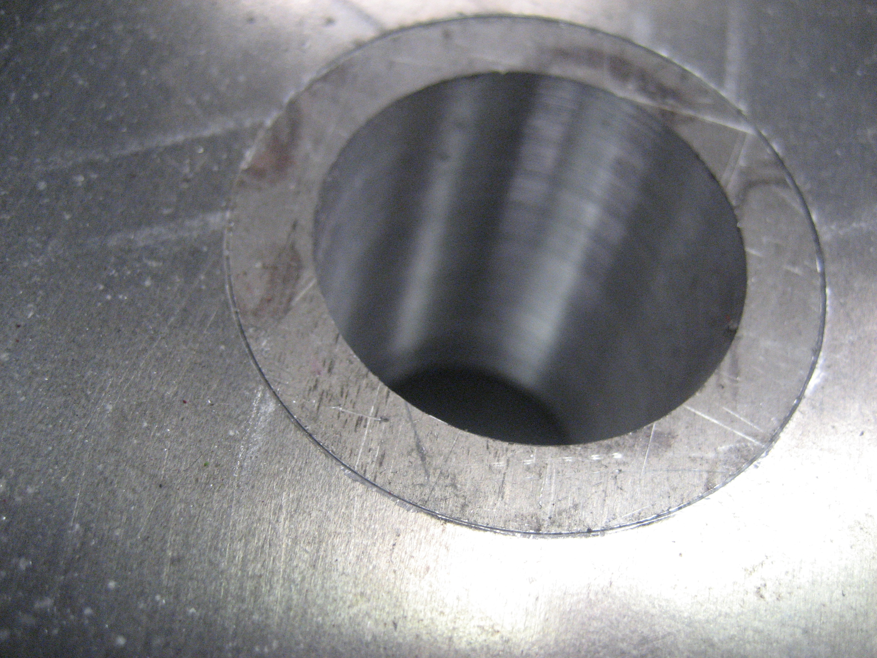
...alas, a perfect fit.

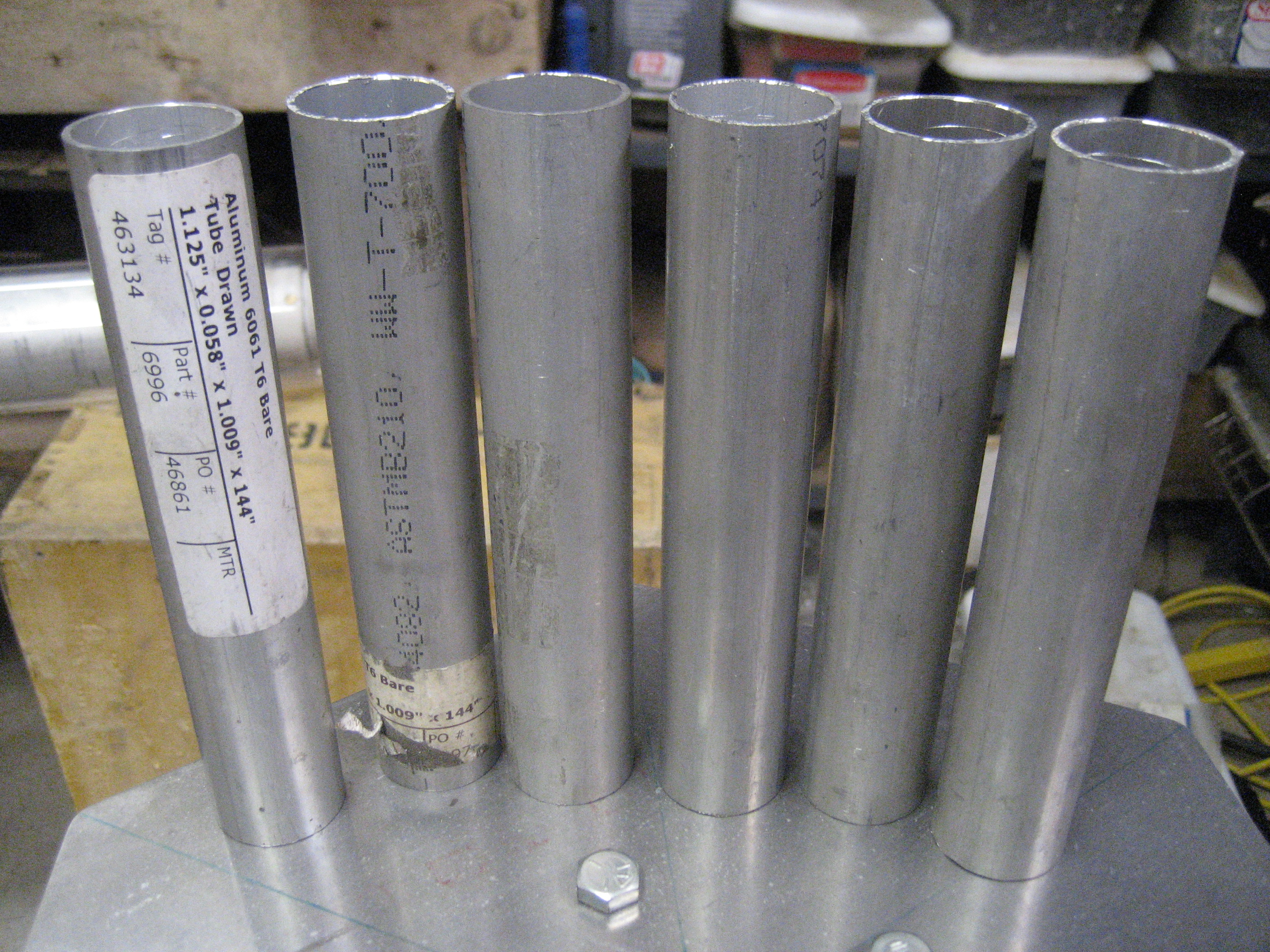
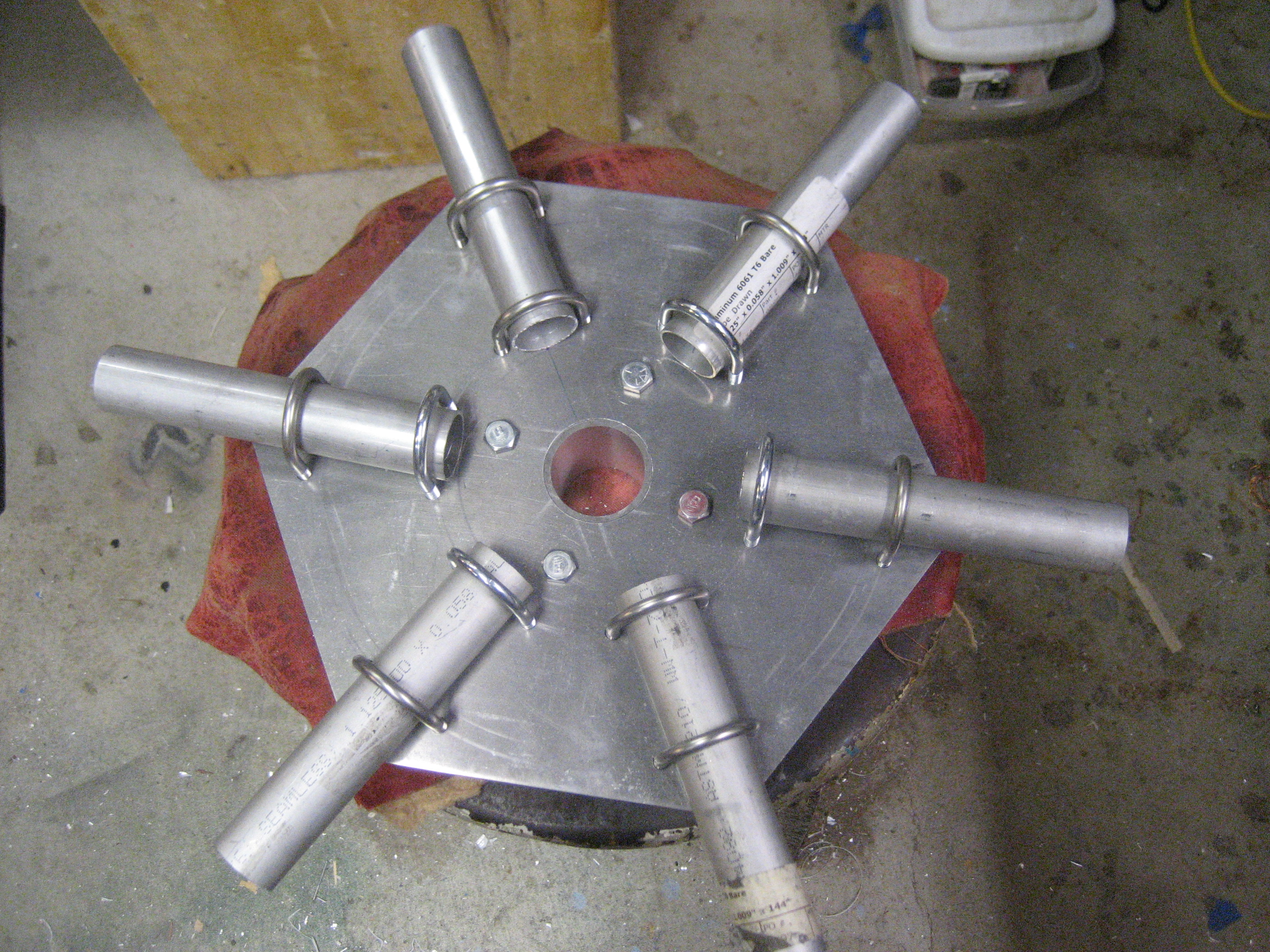
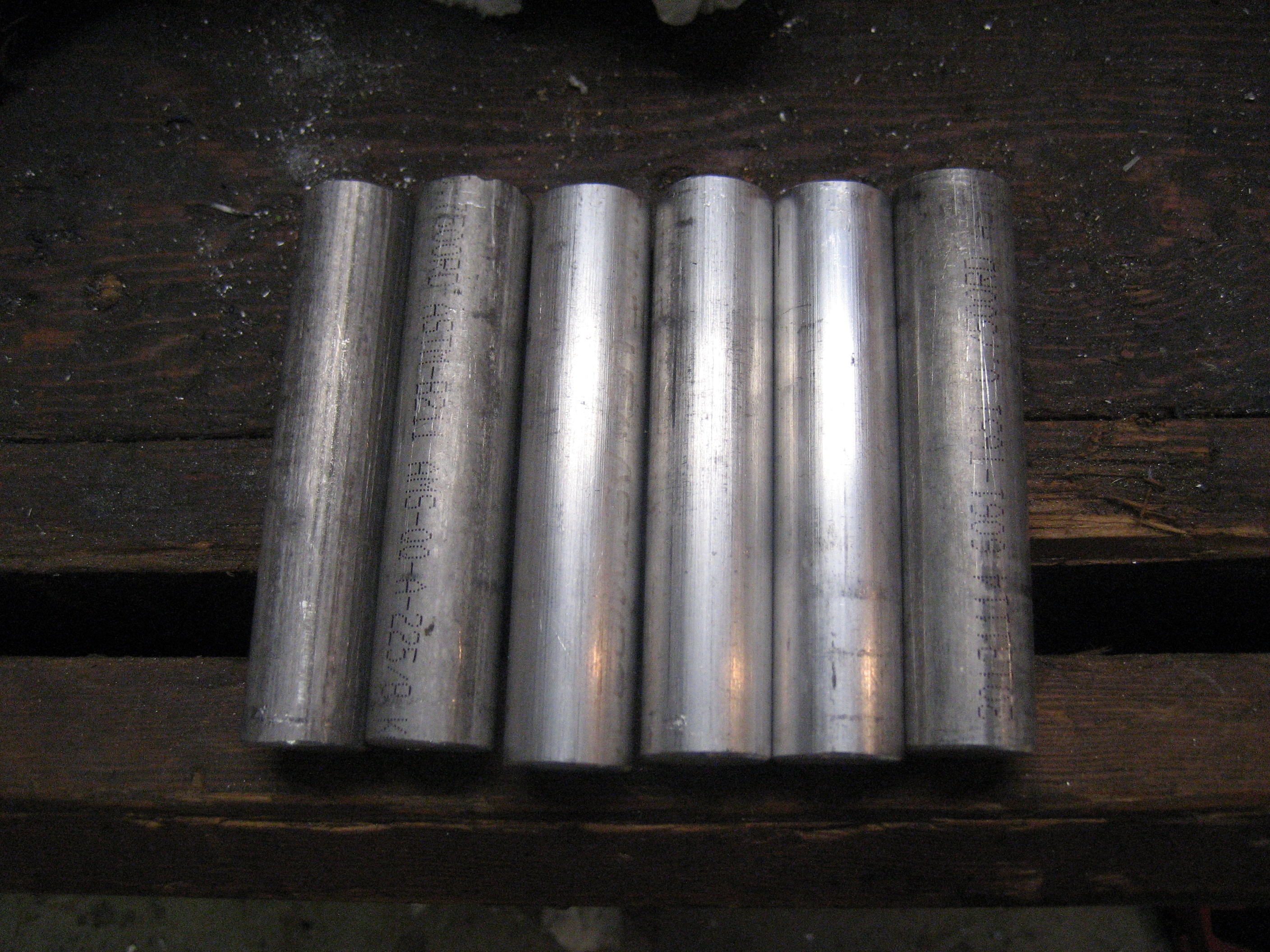
Aluminum "crush tubes" will be put over the end of the fiberglass spreader base under the u-bolts. These were shorts that I got for next to nothing from an in-person visit to OnlineMetals.com.
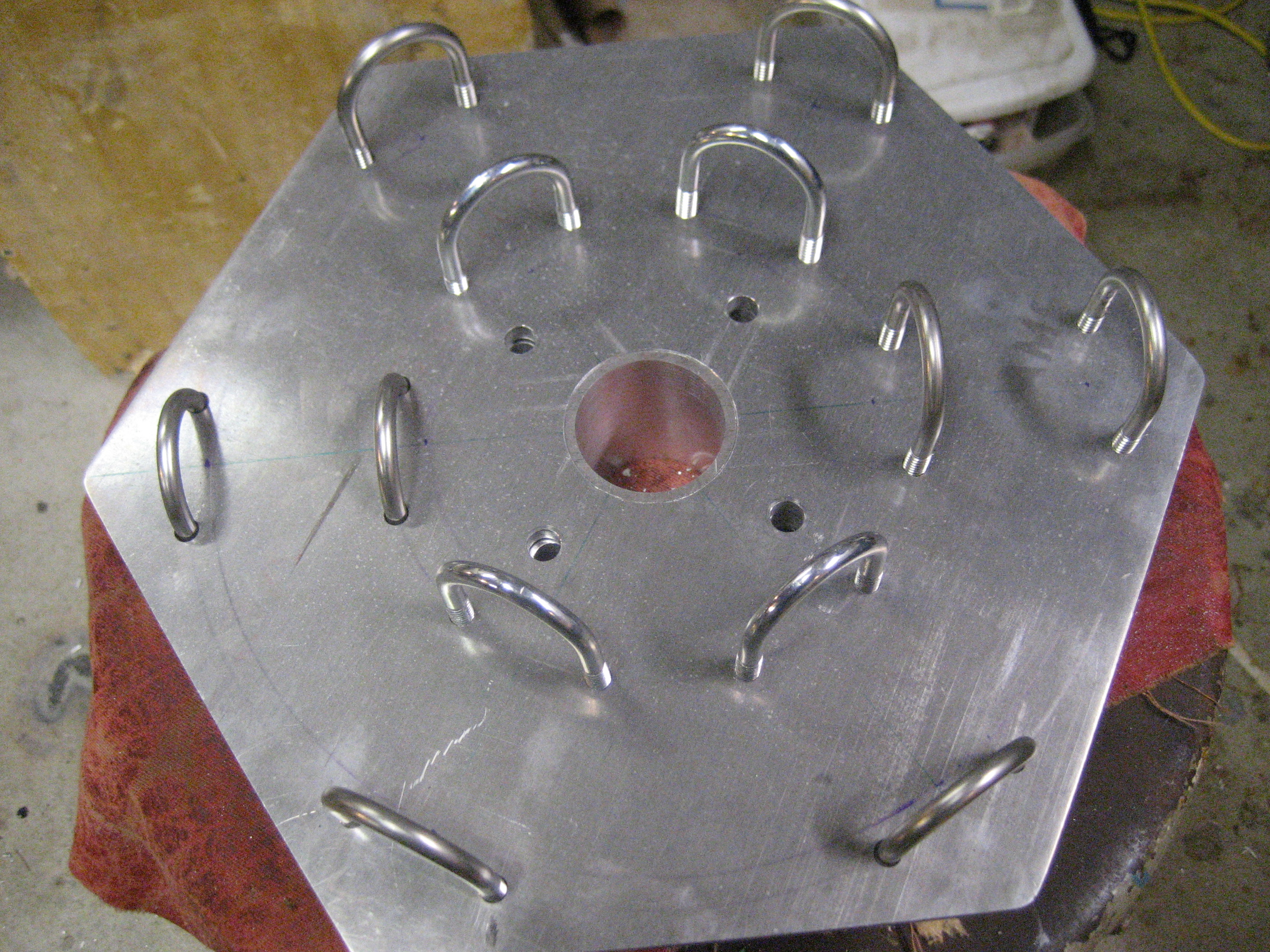
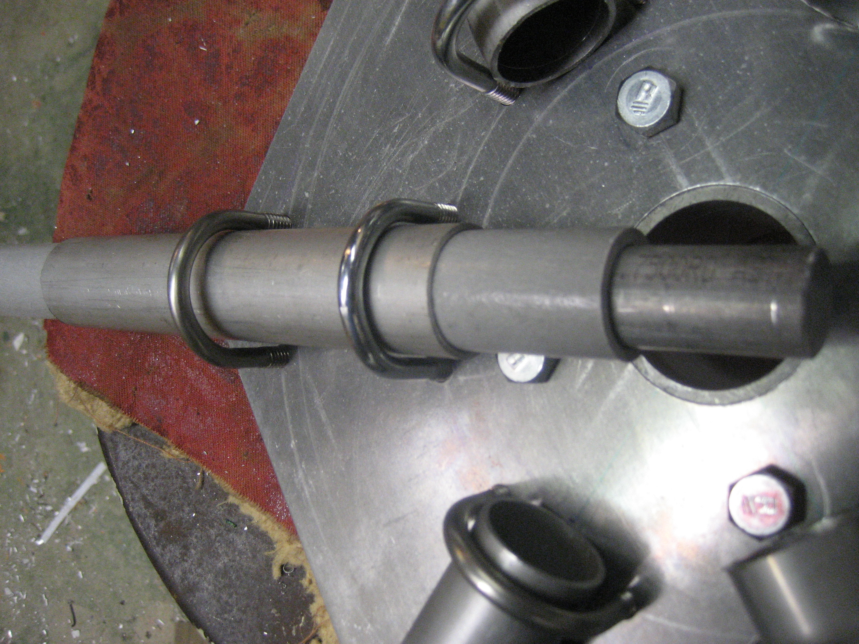
Stainless steel u-bolts were acquired from a local hardware store.
I was going to put these solid aluminum inserts placed inside the base of each spreader. Eventually I opted to leave them out. Plugging the end of the spreader seems ill-advised....
...how would the water get out?
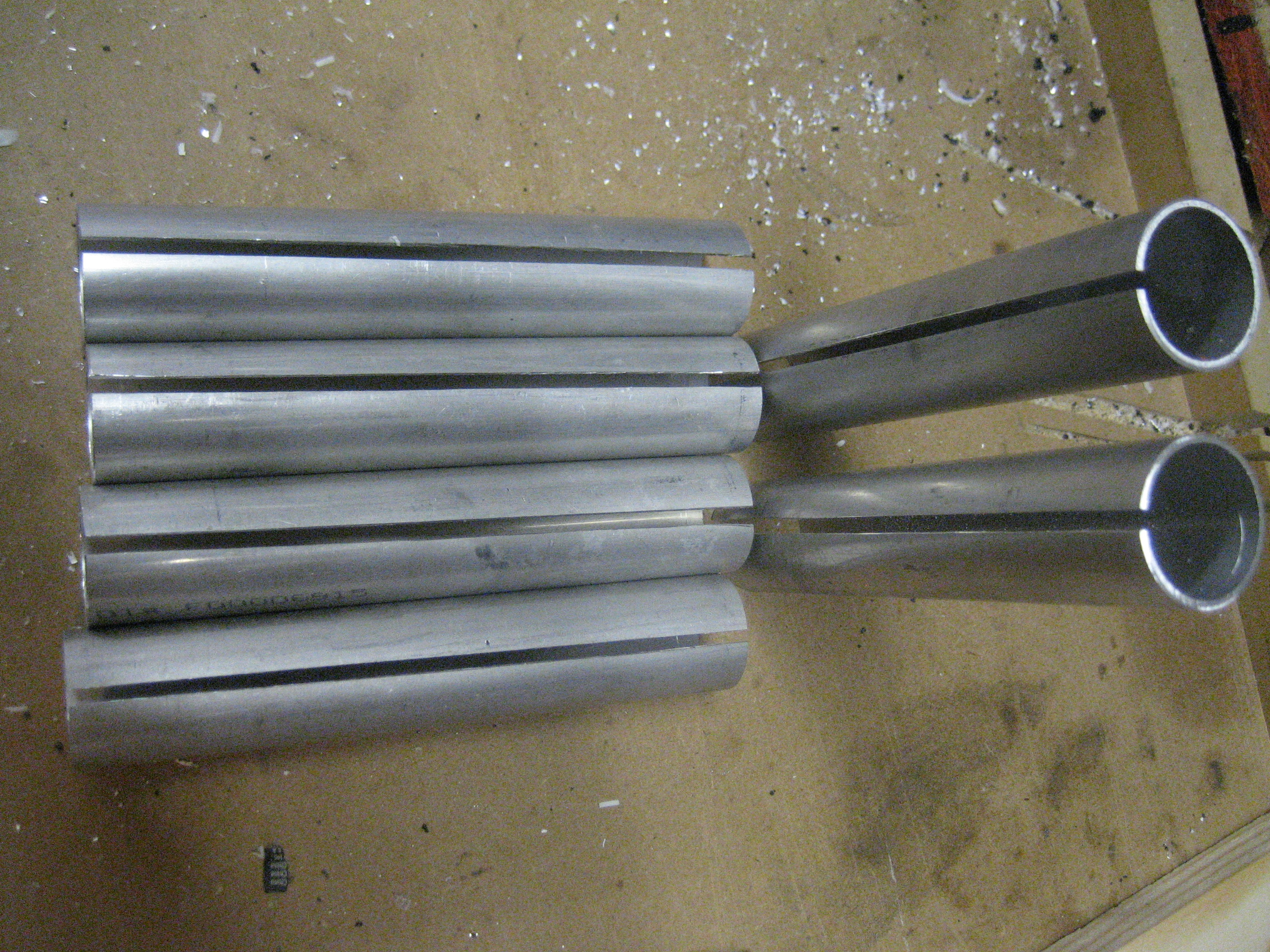
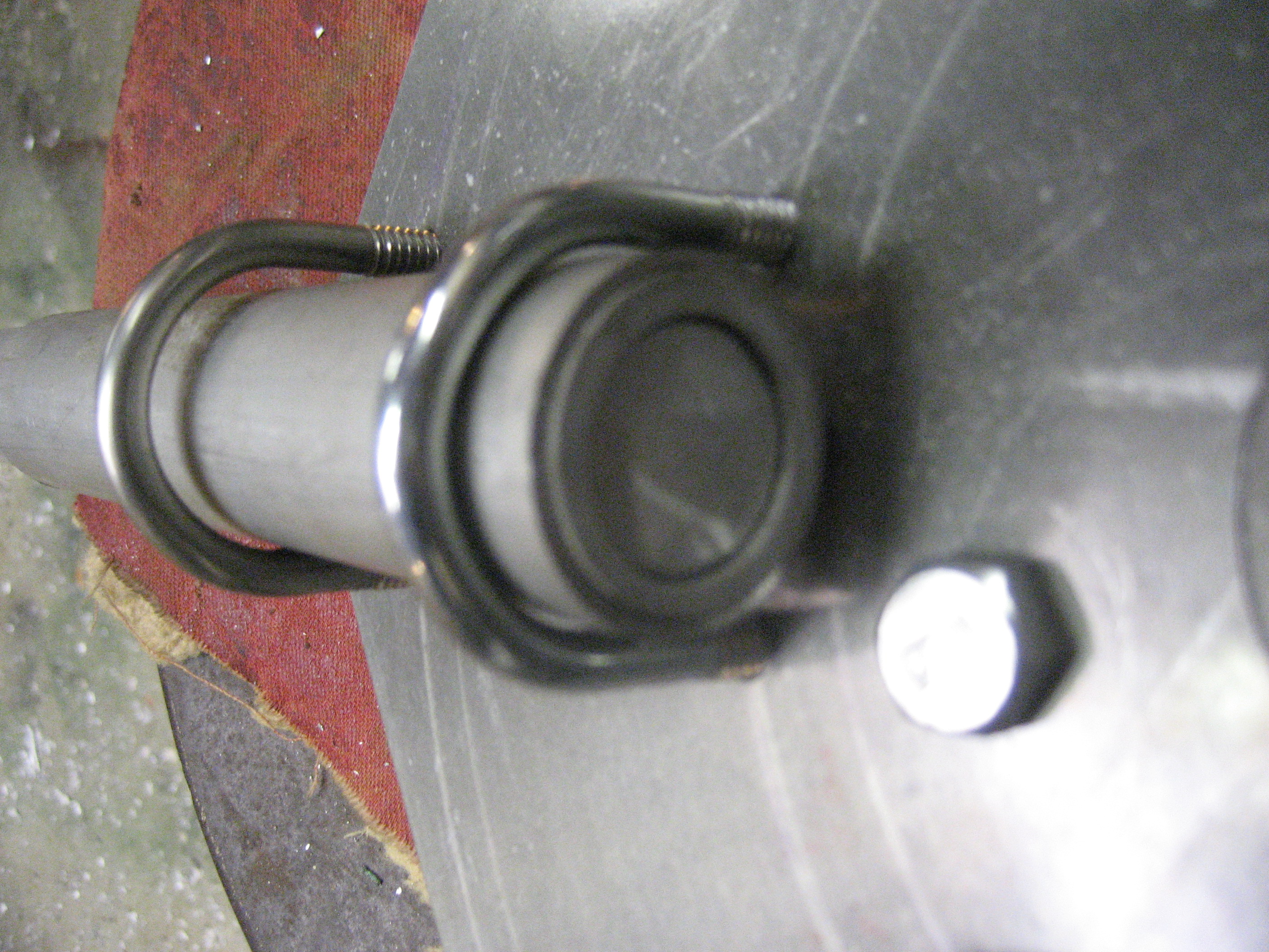
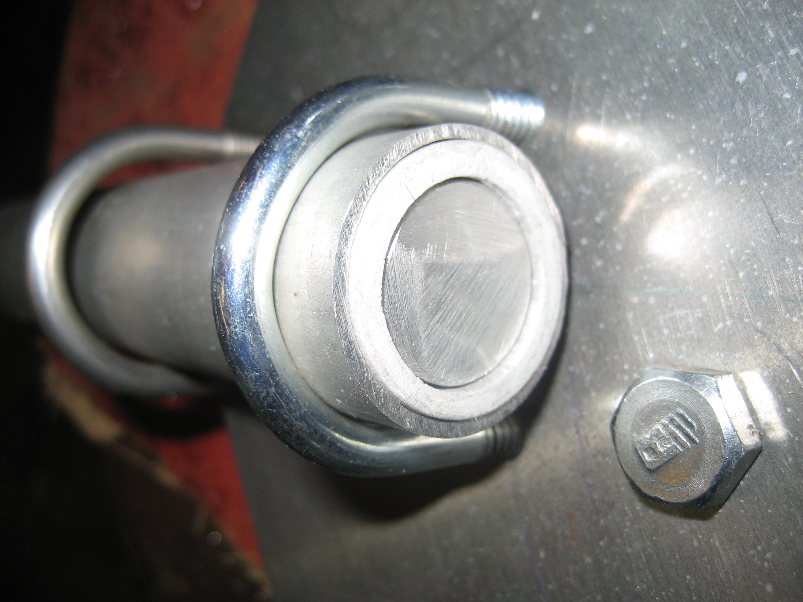
Slots sawn into the crush tube.
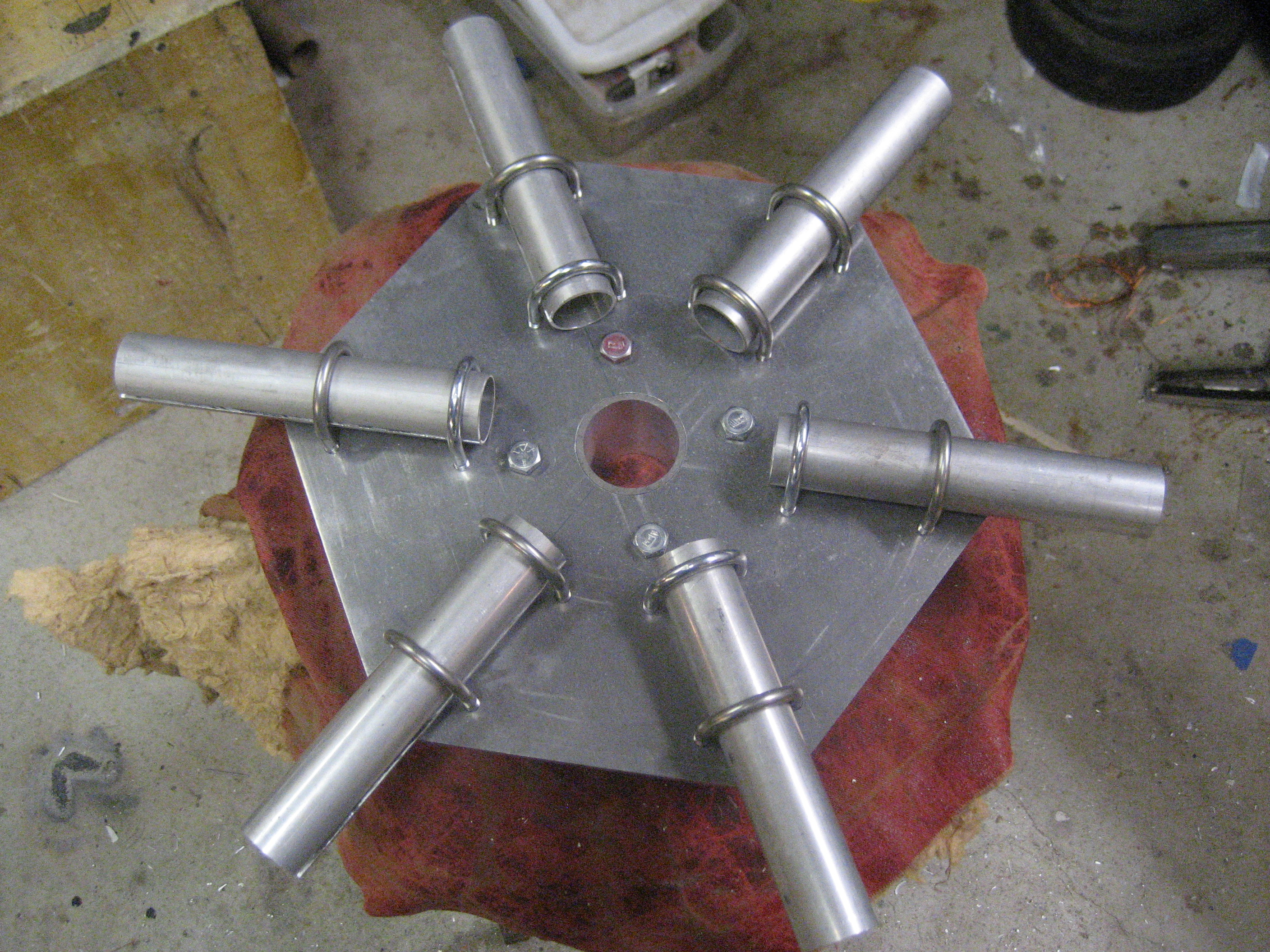
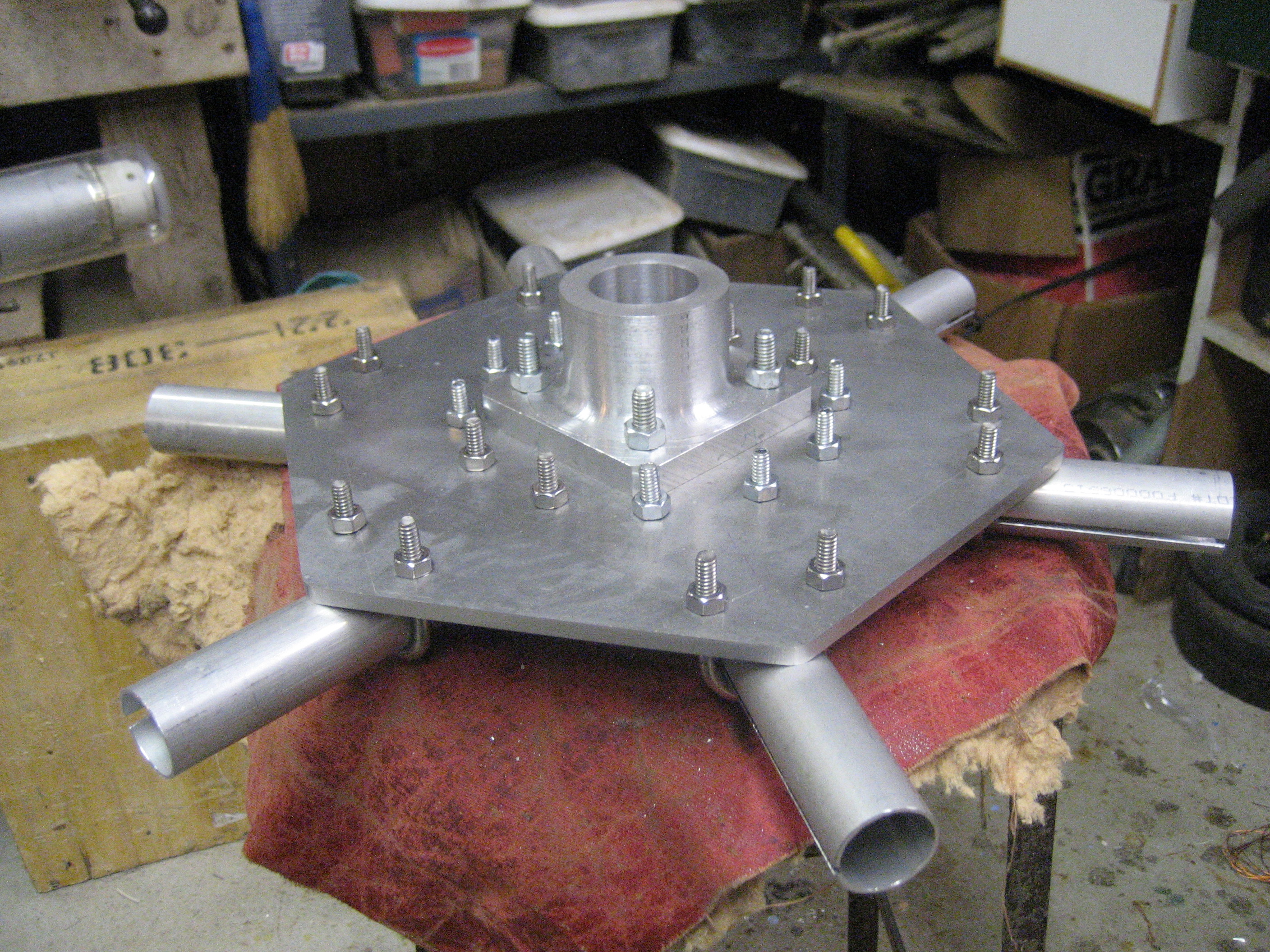
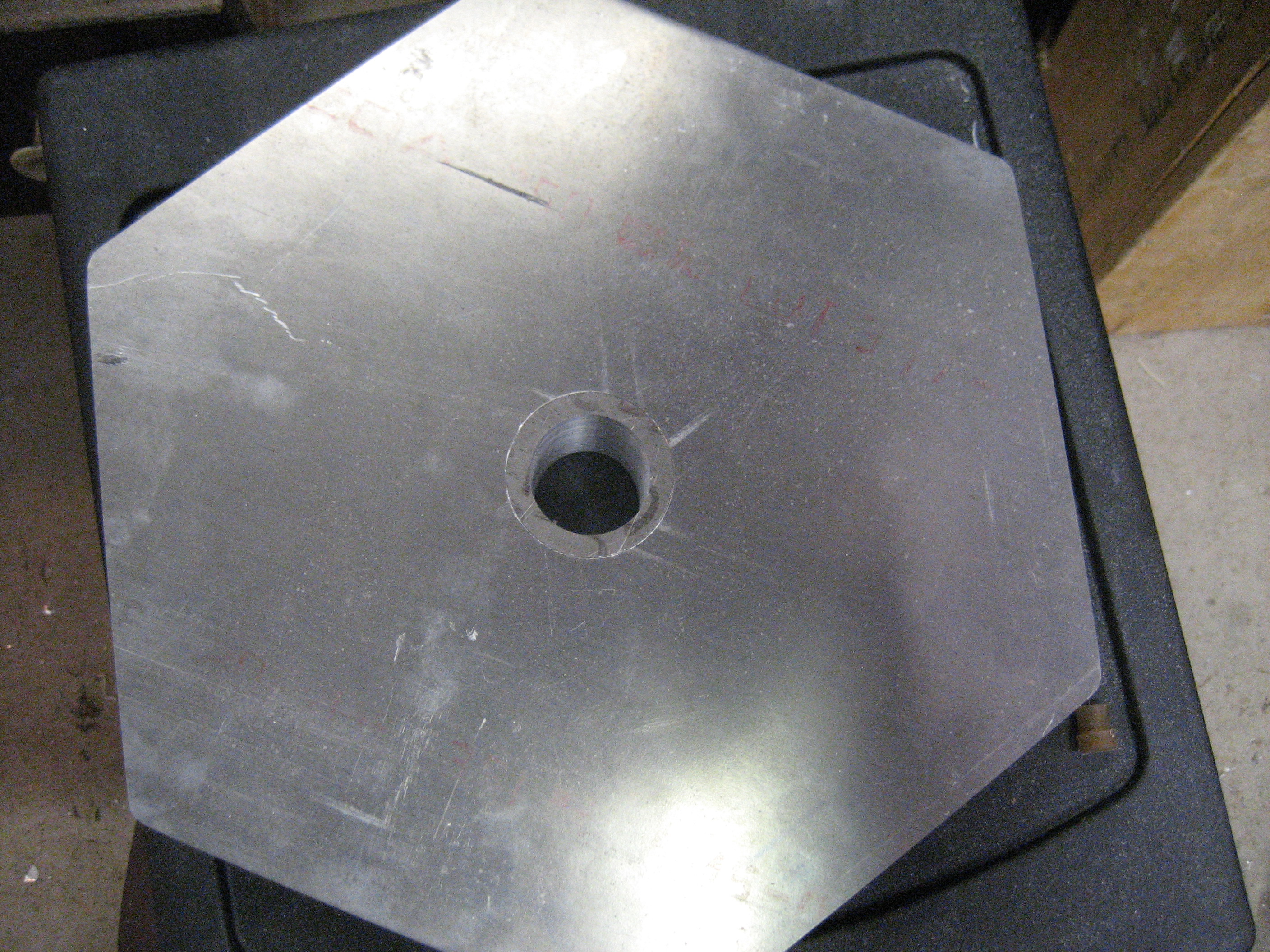
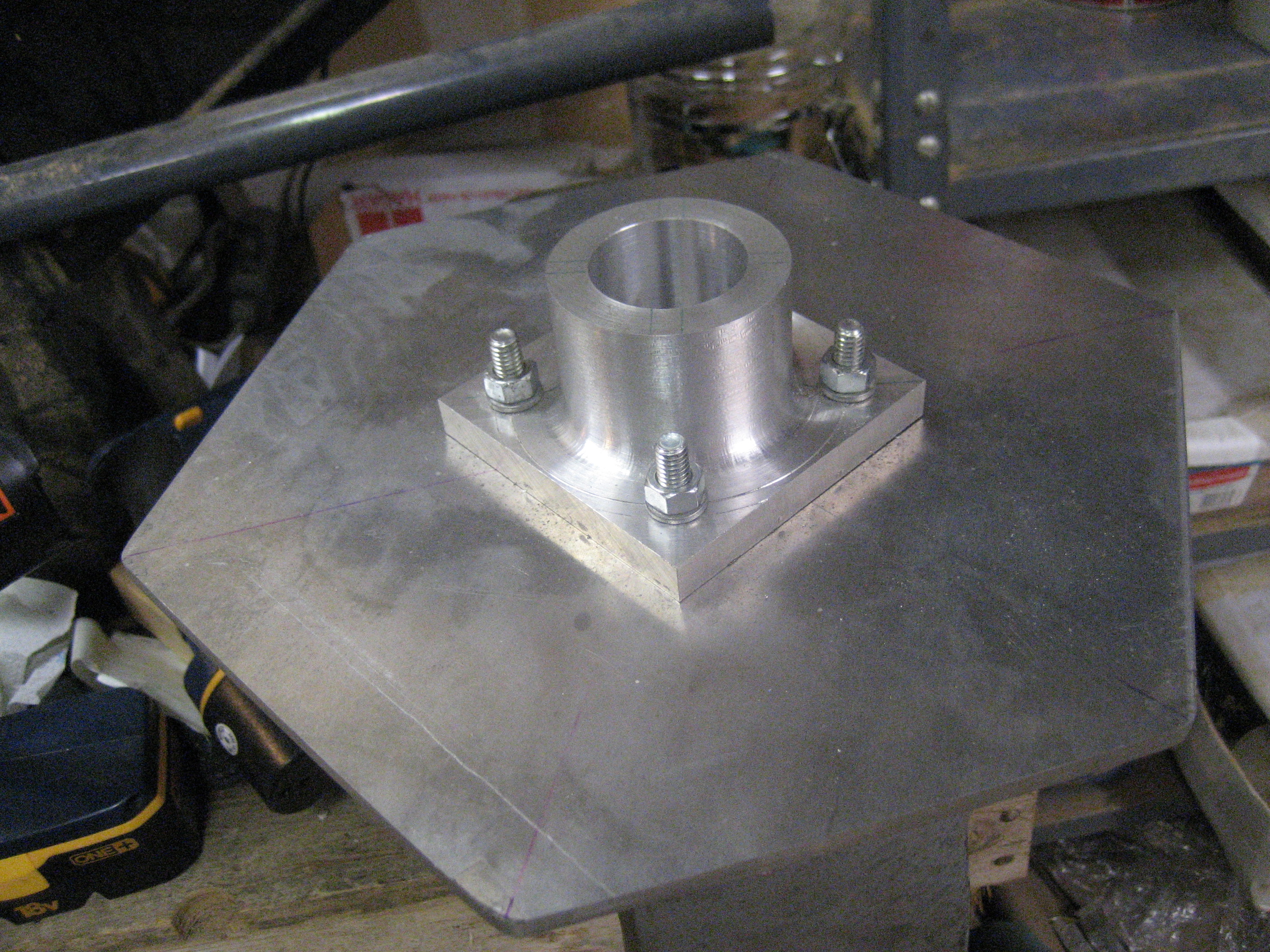
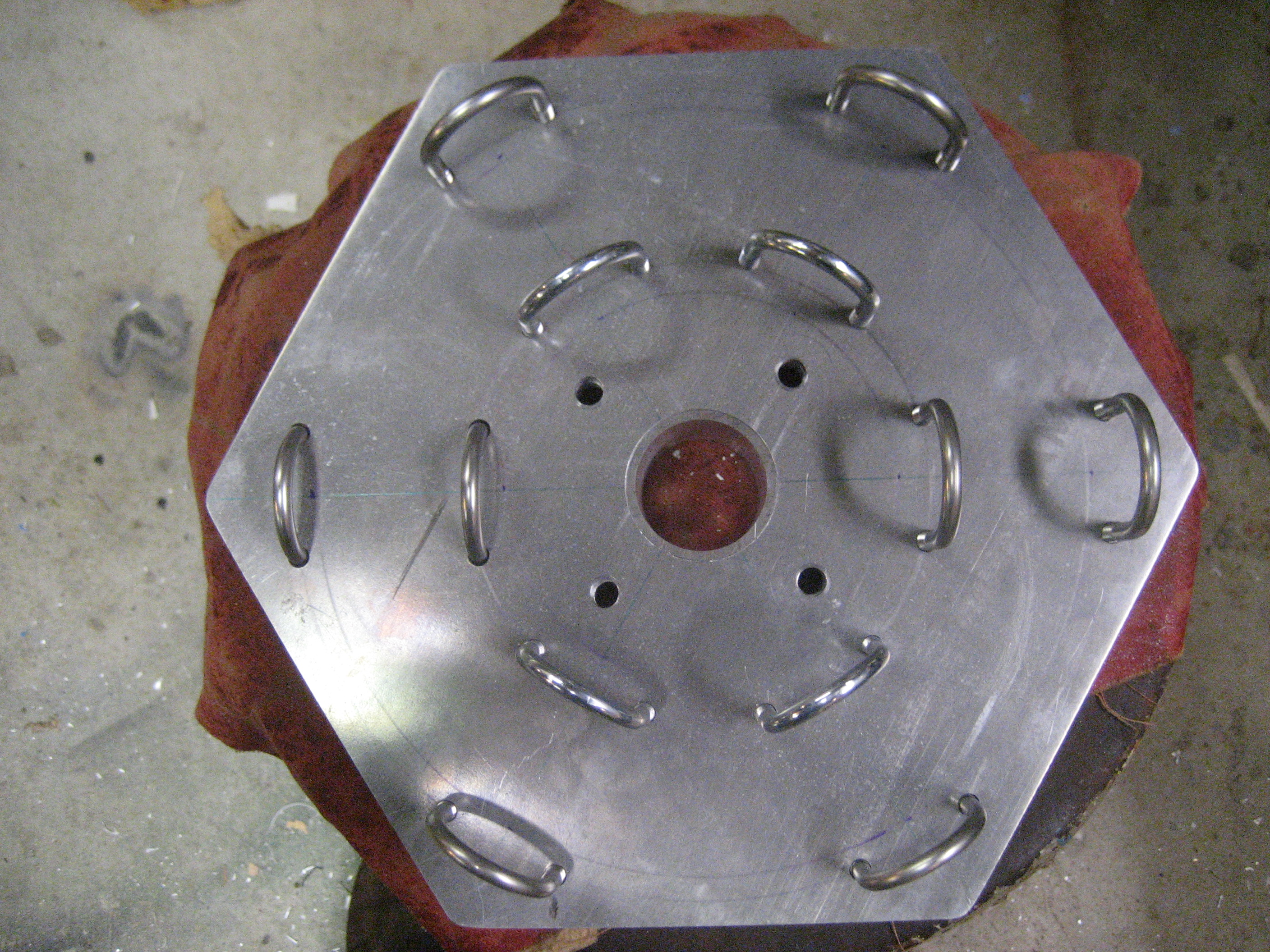
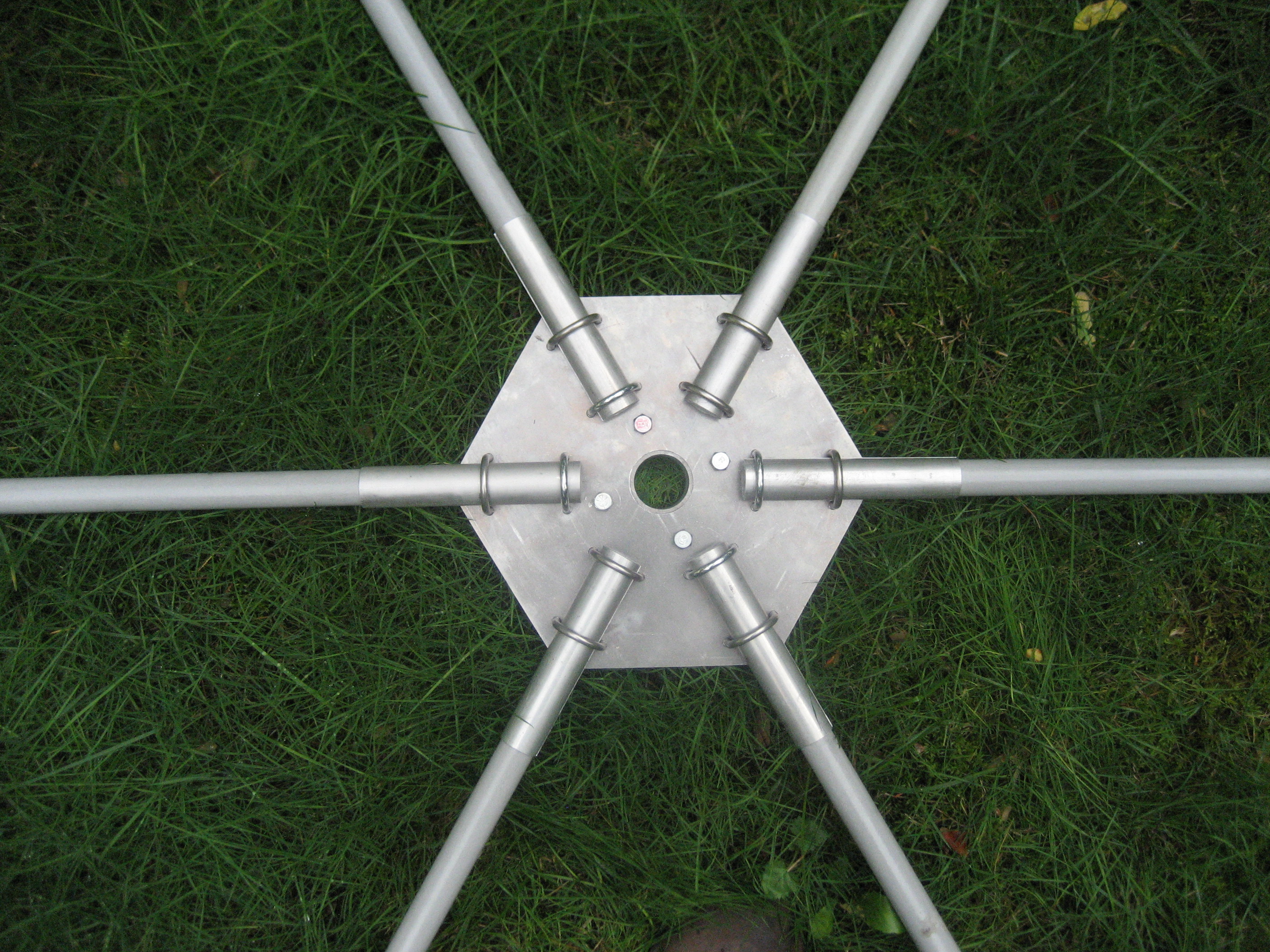
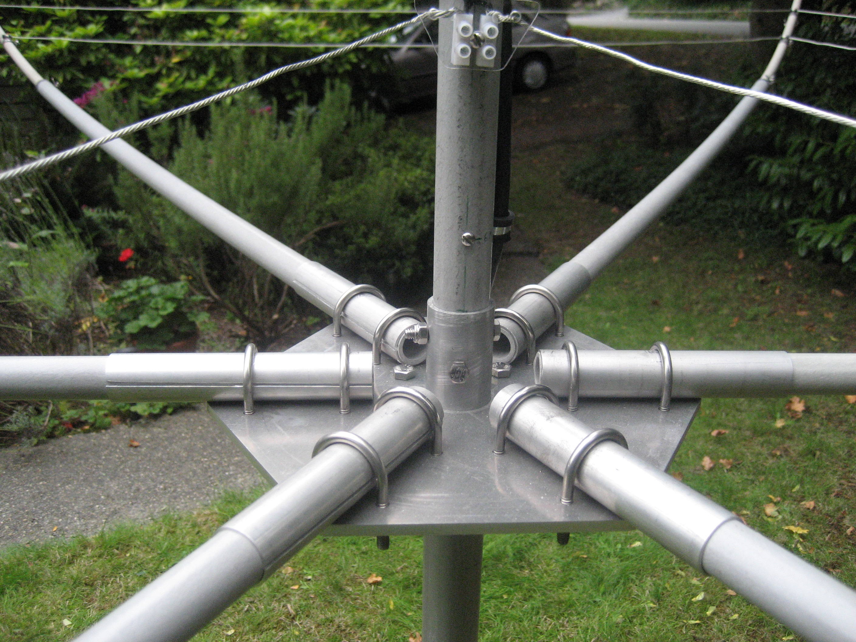
The mostly-finished base plate.
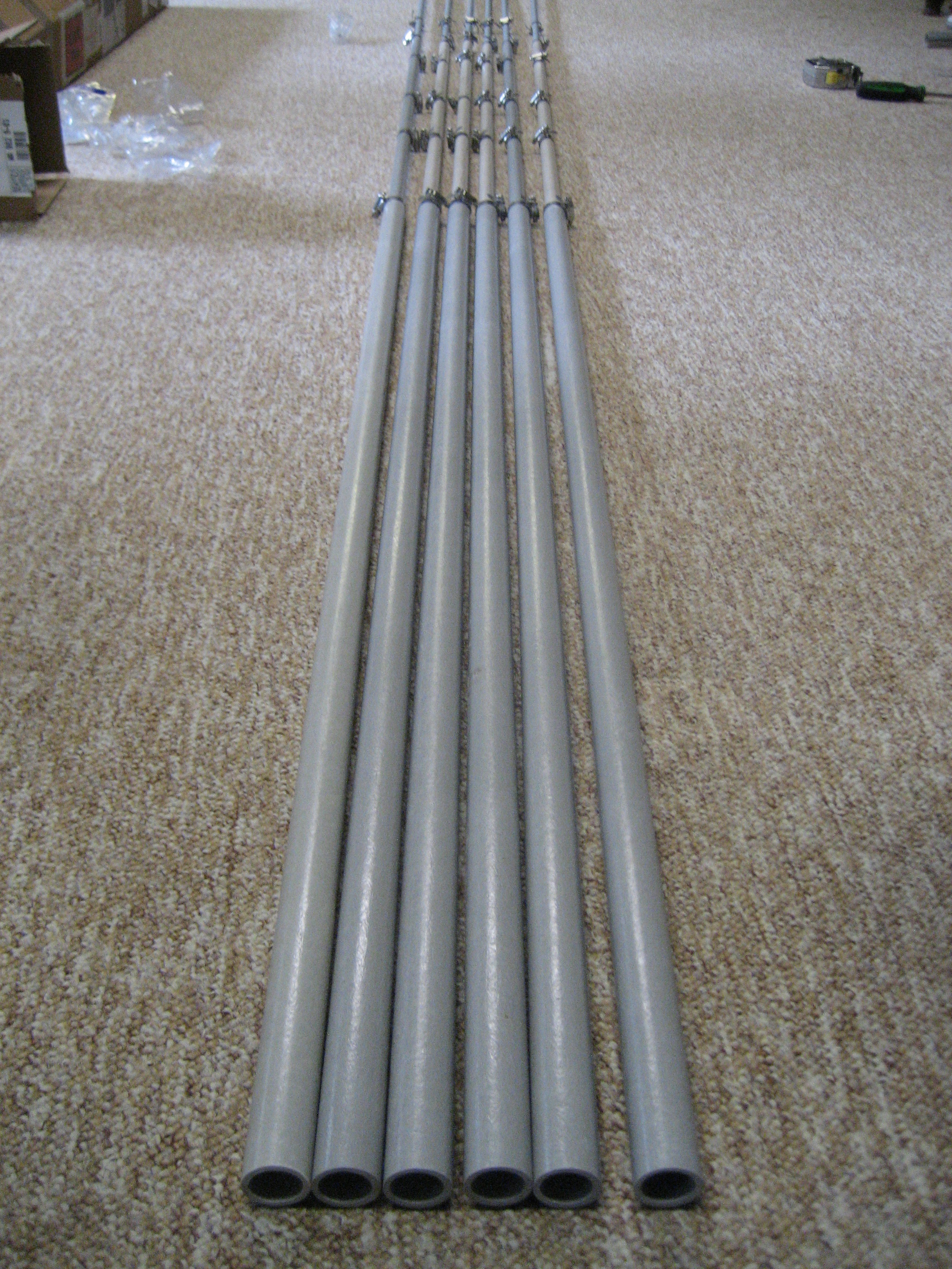
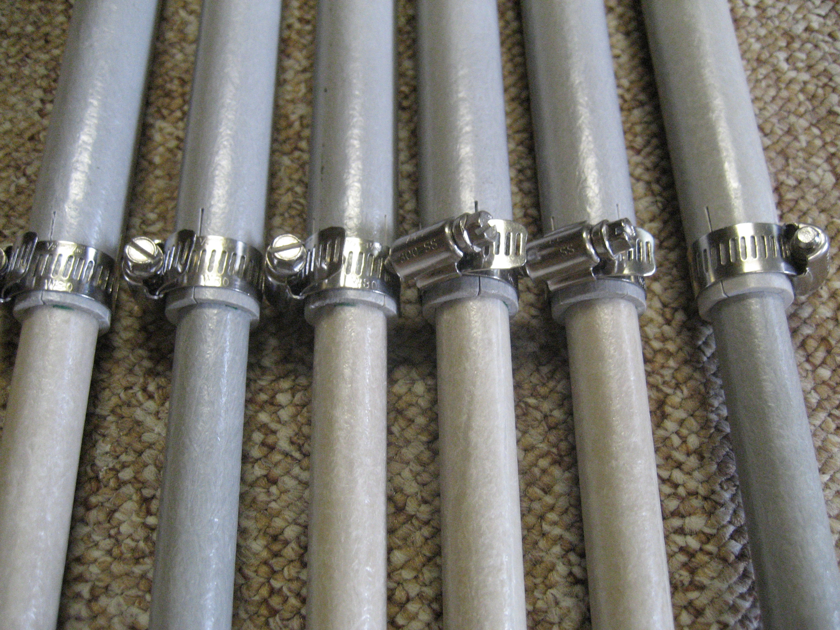
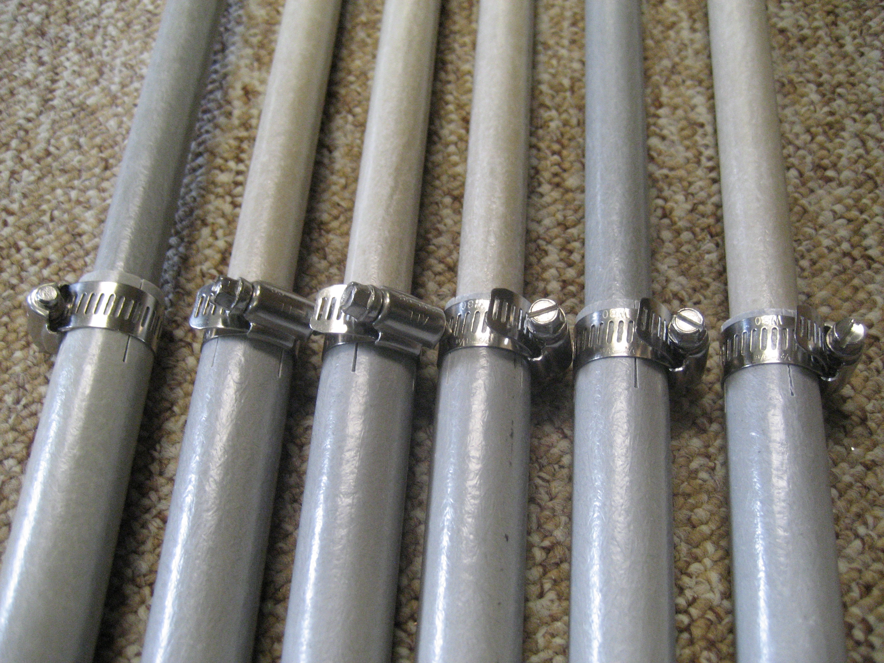
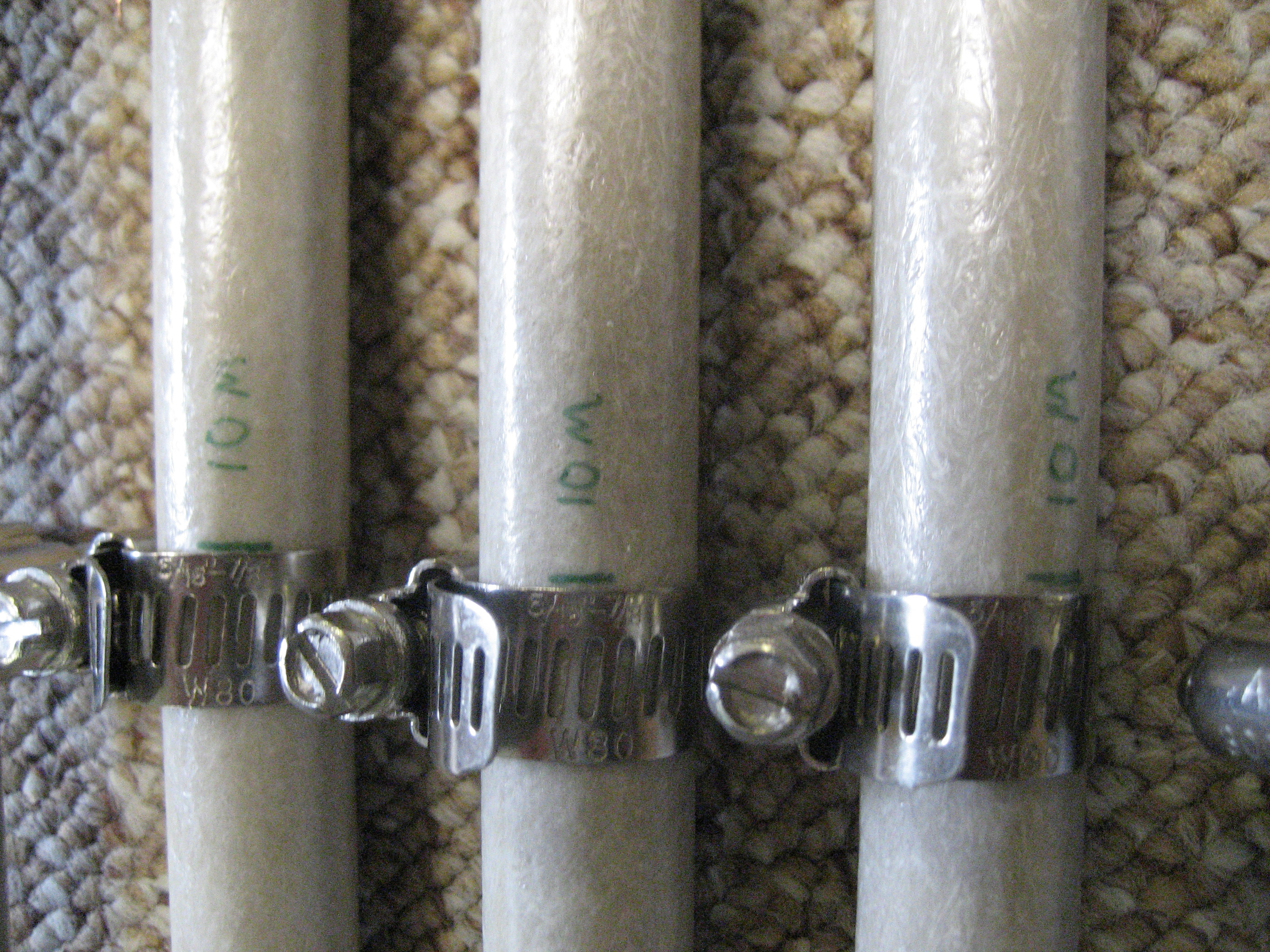
Telescoping fiberglass tubes turned into spreaders.
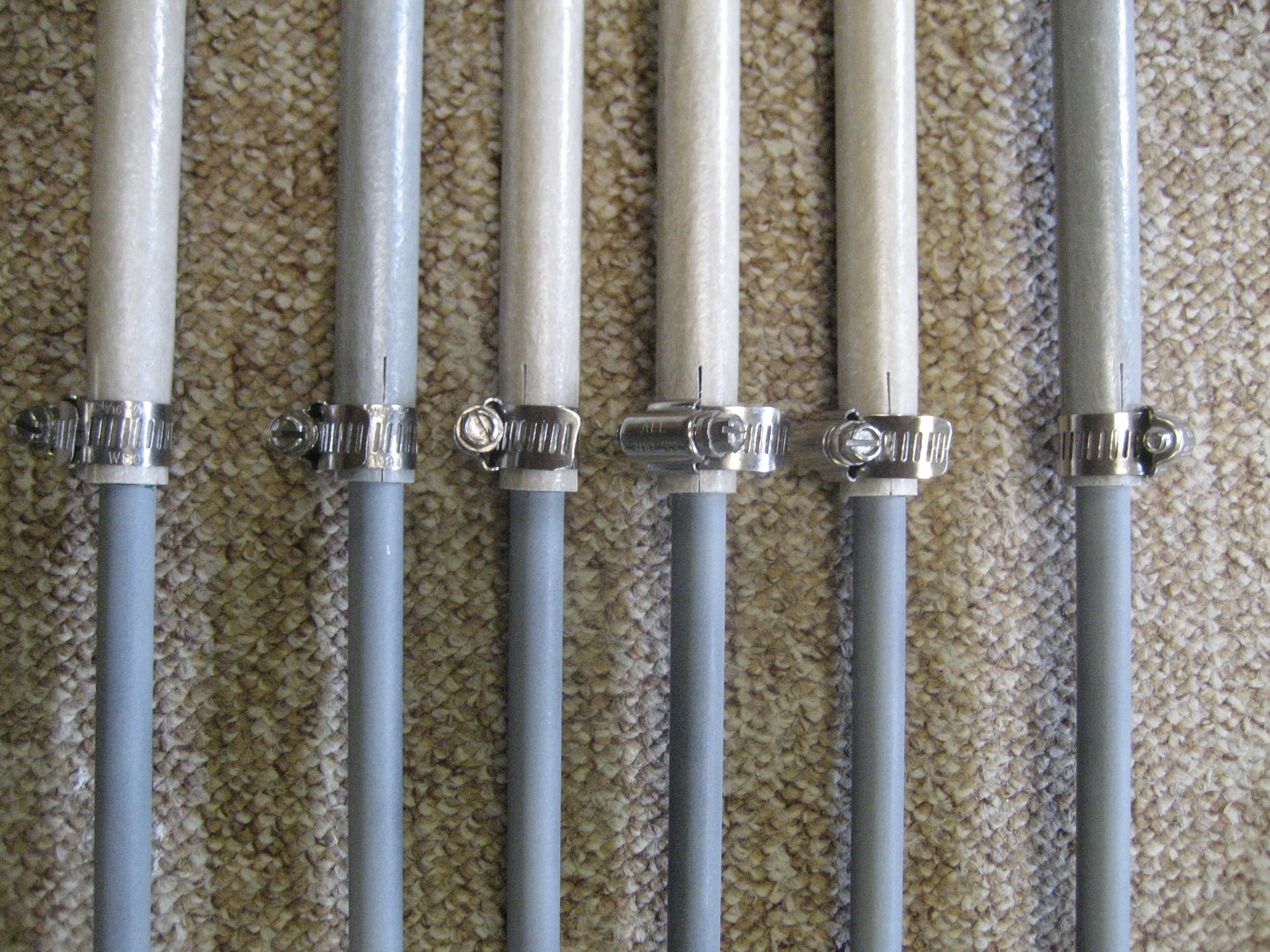
The hose clamps are stainless, of course.
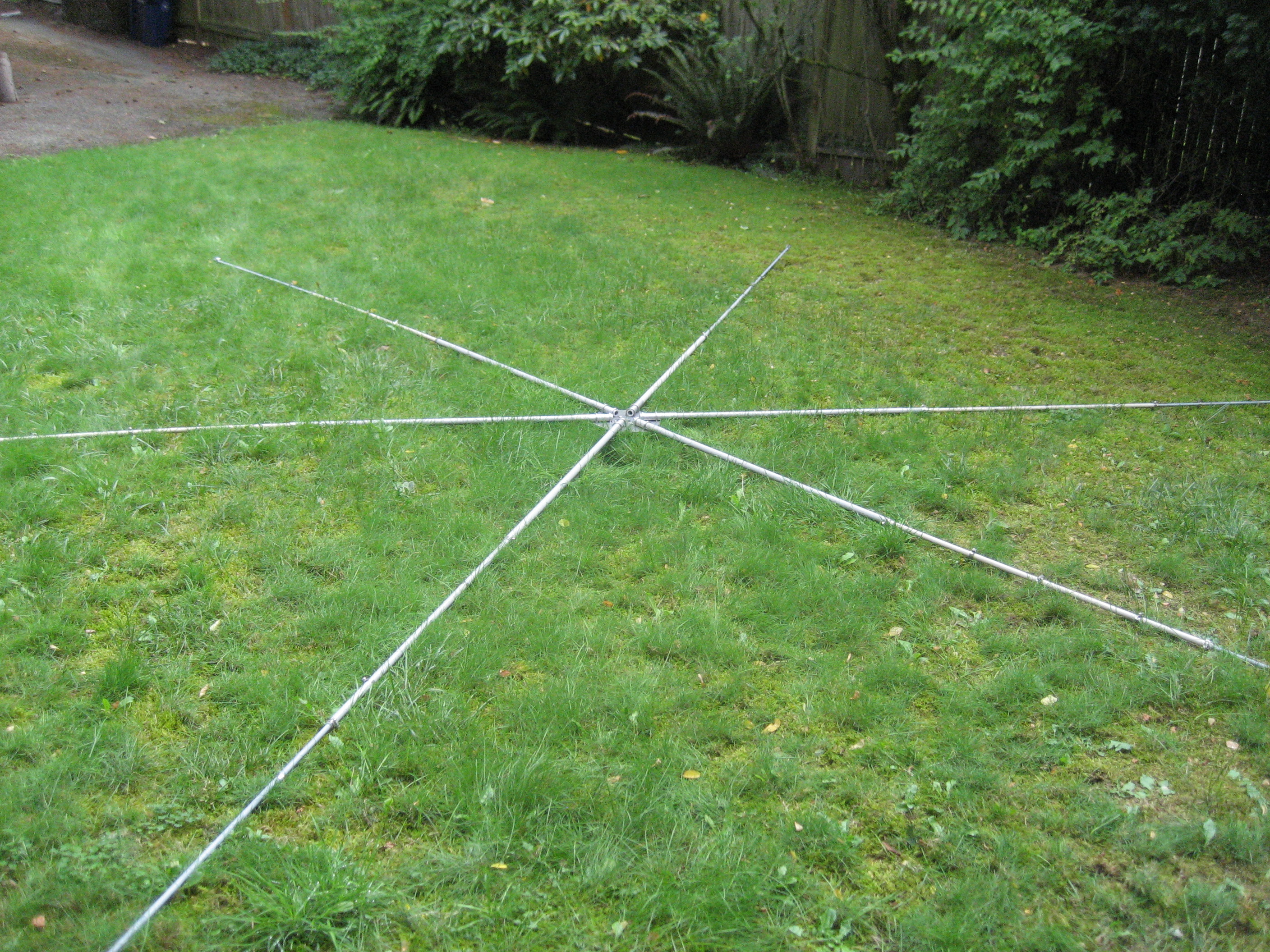
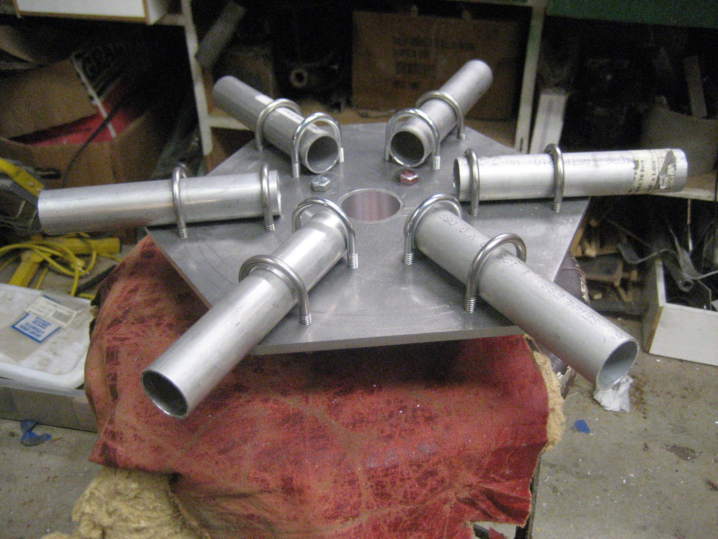
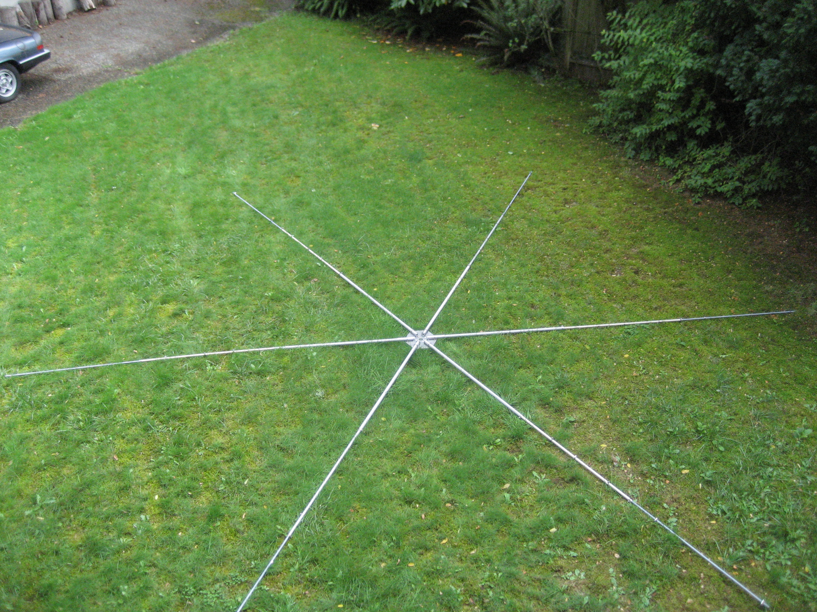
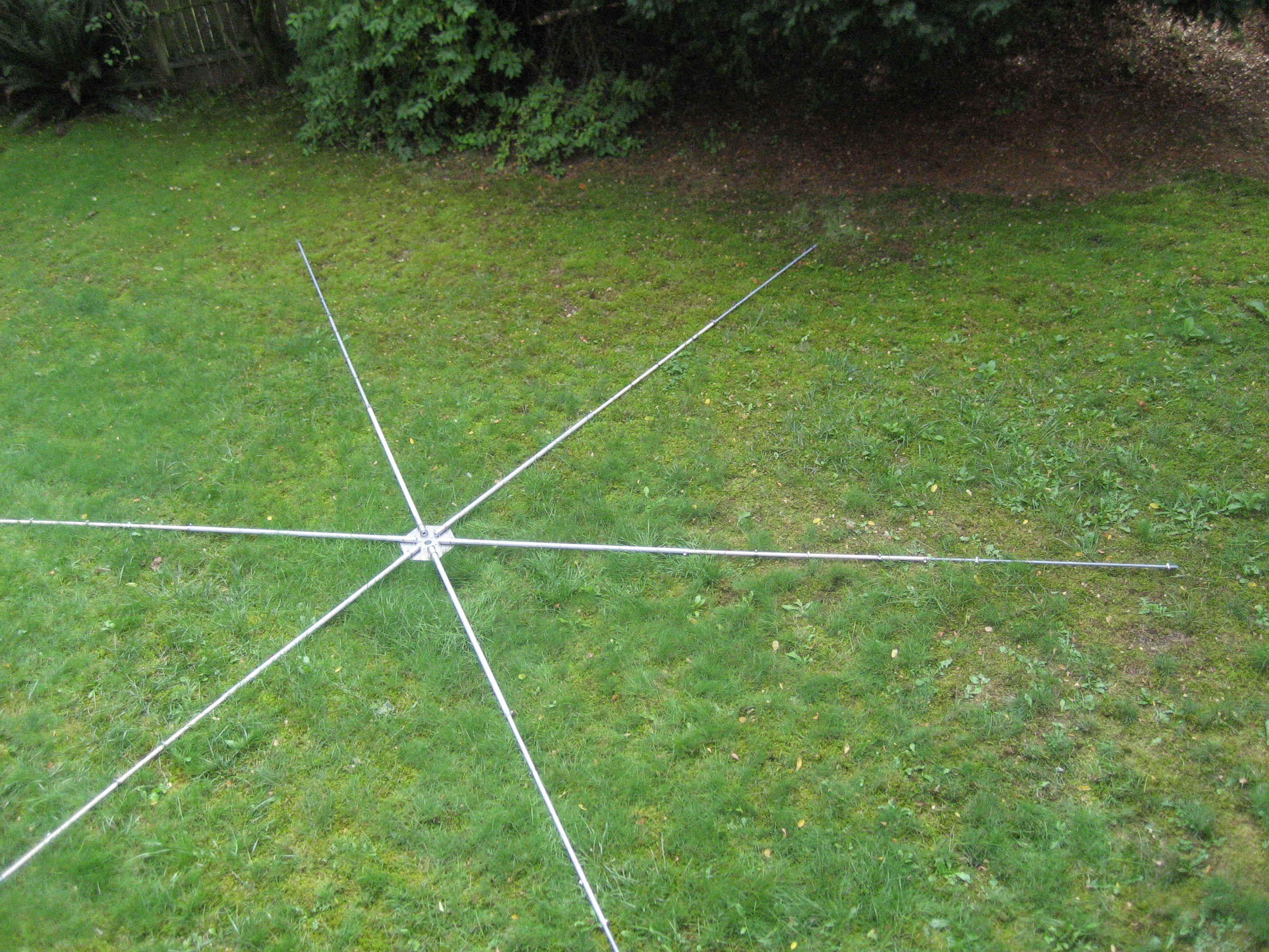
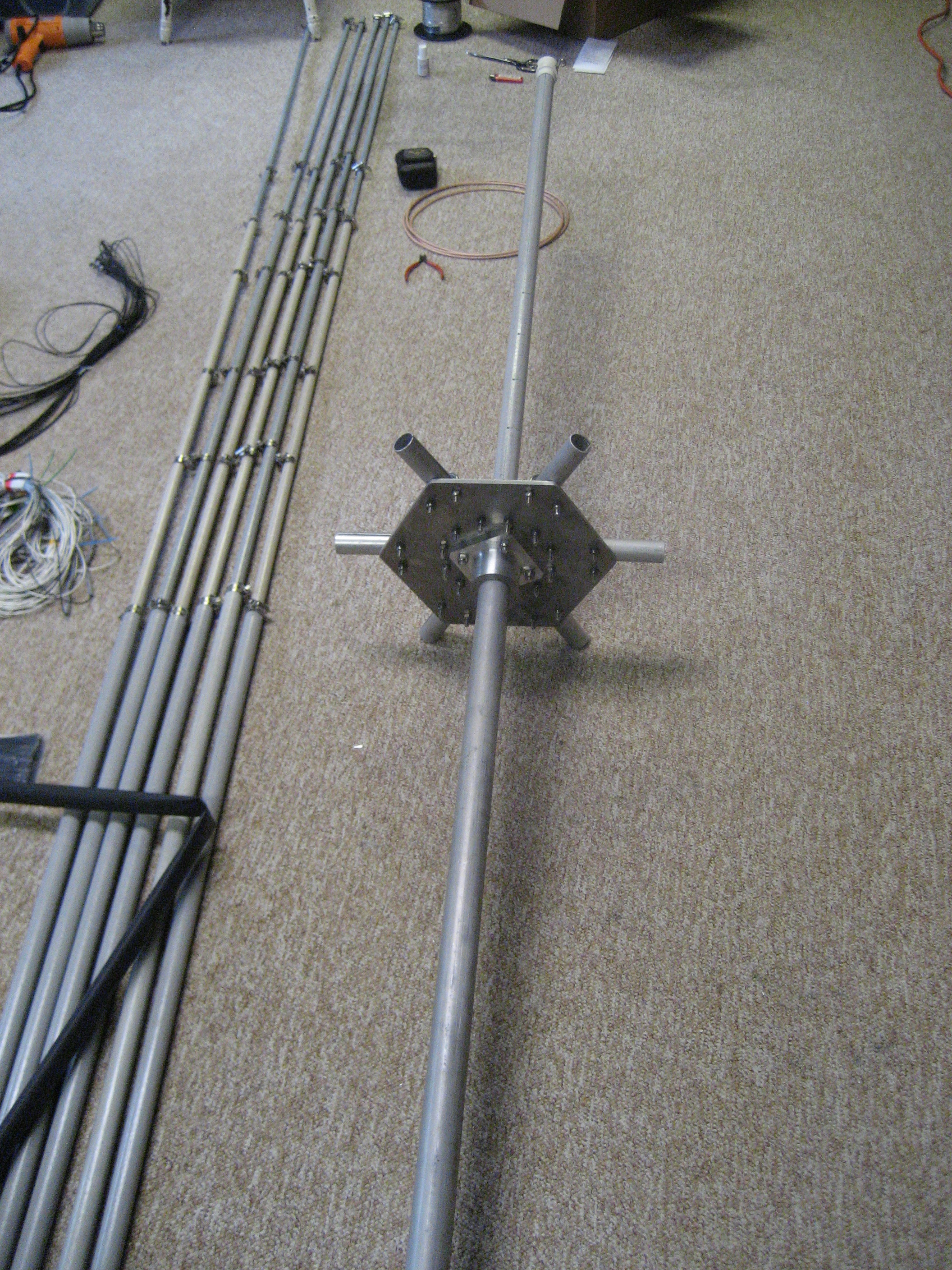
Hub and spreaders laid out in the back yard.
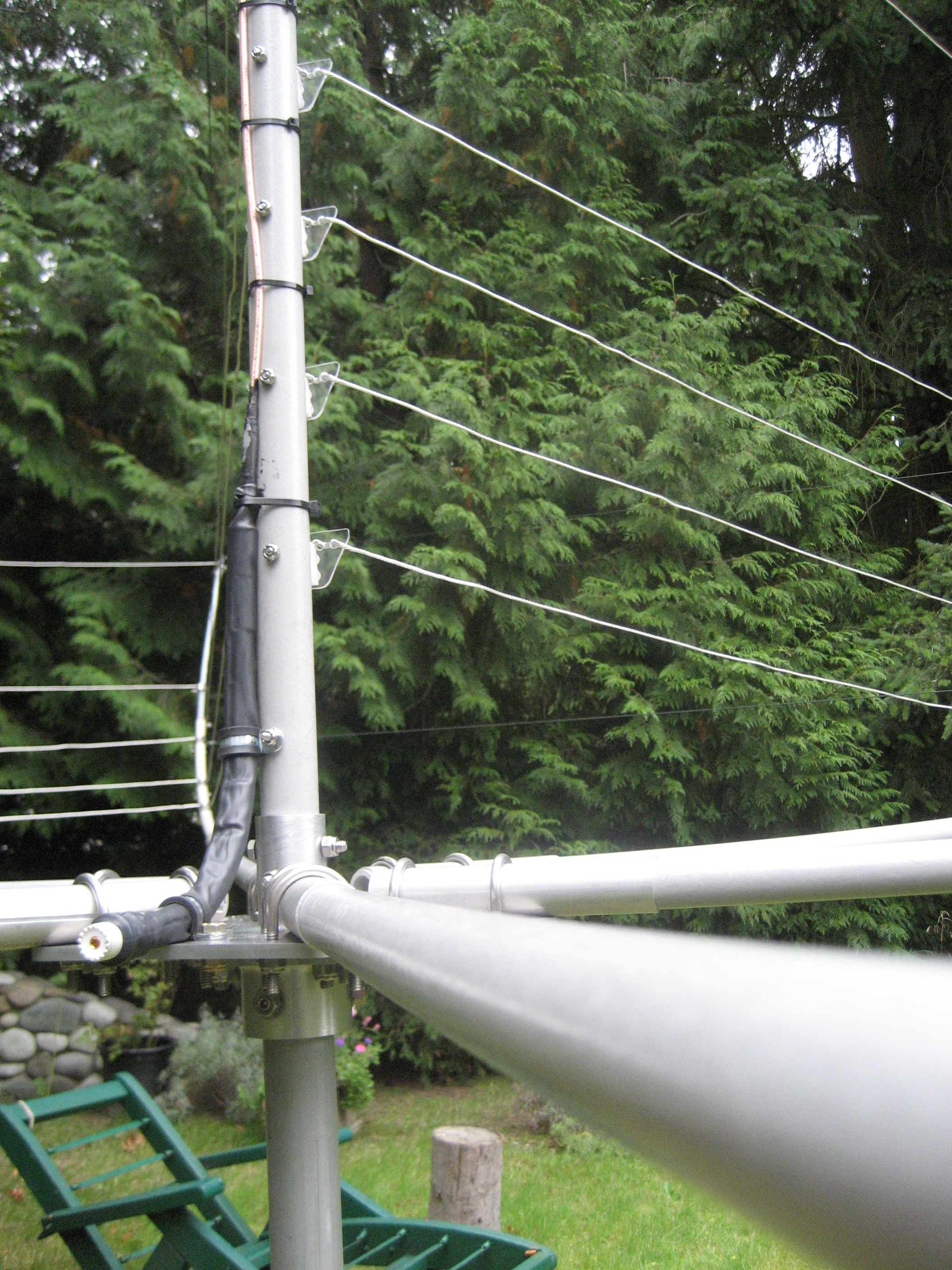
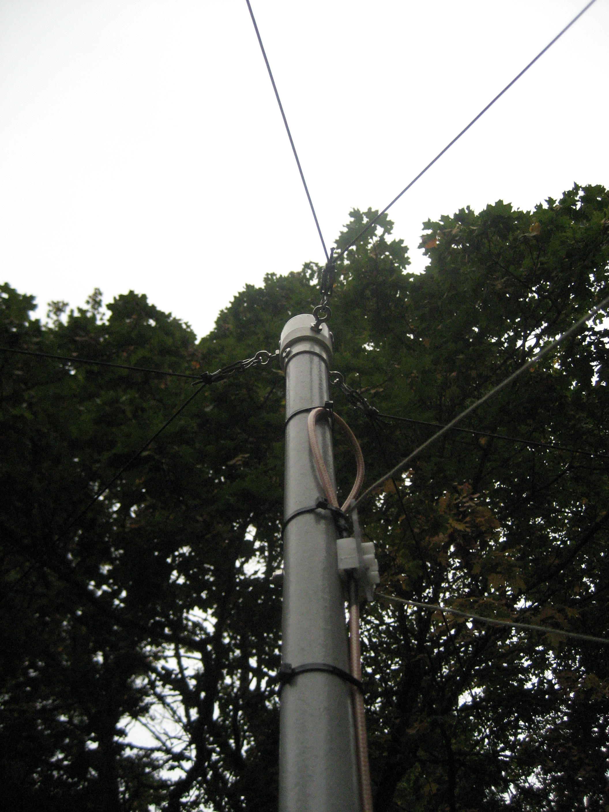
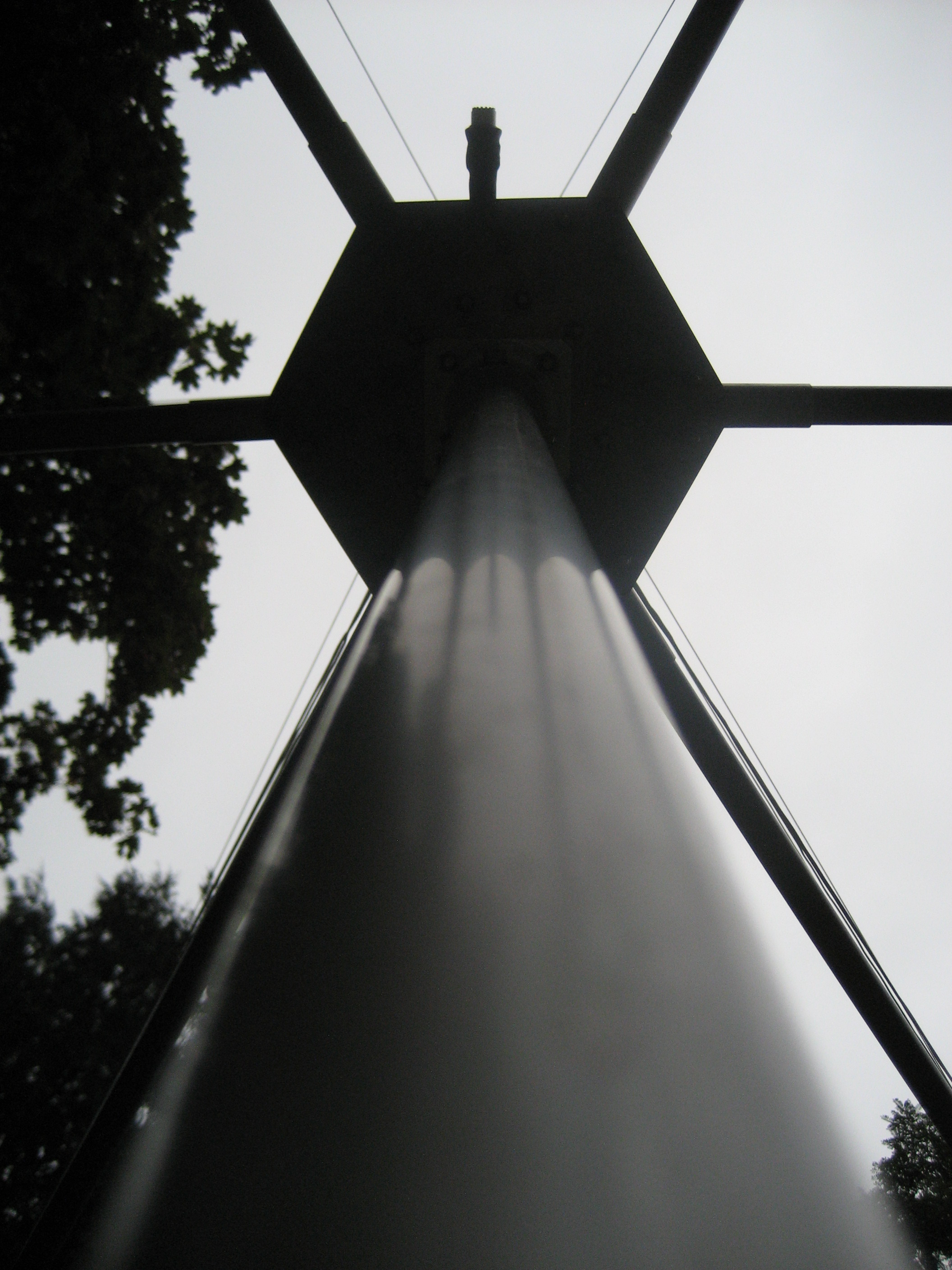
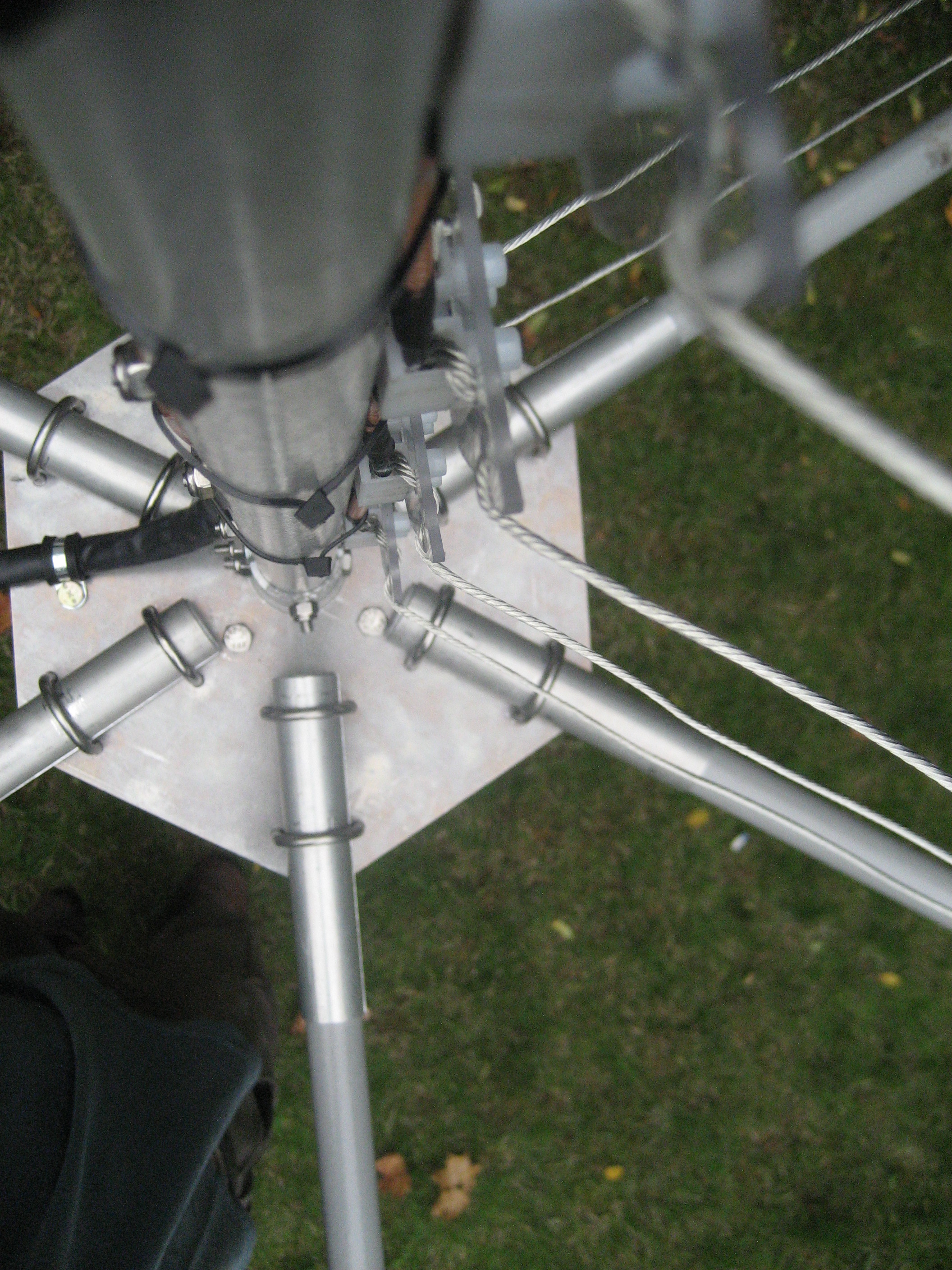
I modified the design of the center post cap, to allow me to add a small VHF or UHF beam above the hex beam (more later). Metal hardware is stainless steel.
Wire elements with 0.075 inch kevlar/dacron cord spliced between driven and reflector elements. the connections have heat-shrink tubing over them.
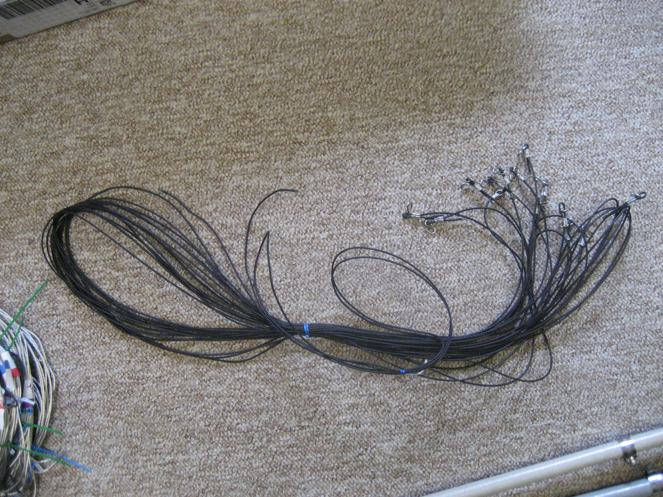
Here are the kevlar/dacron tension cords
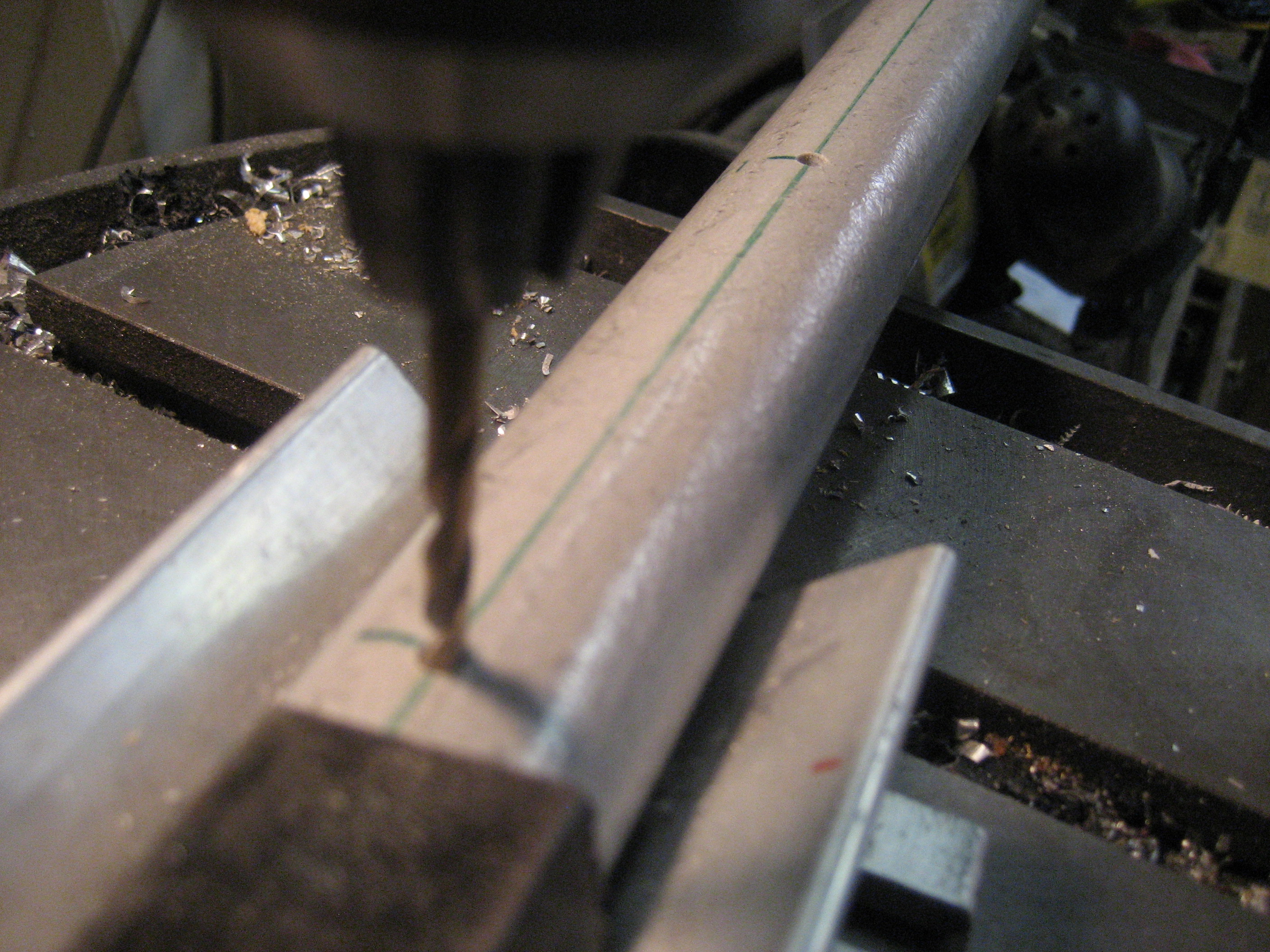
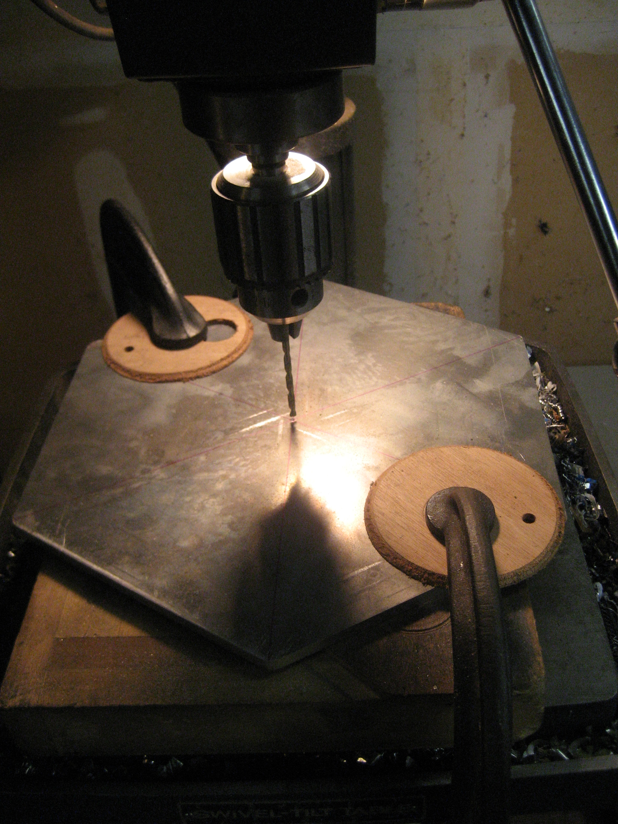
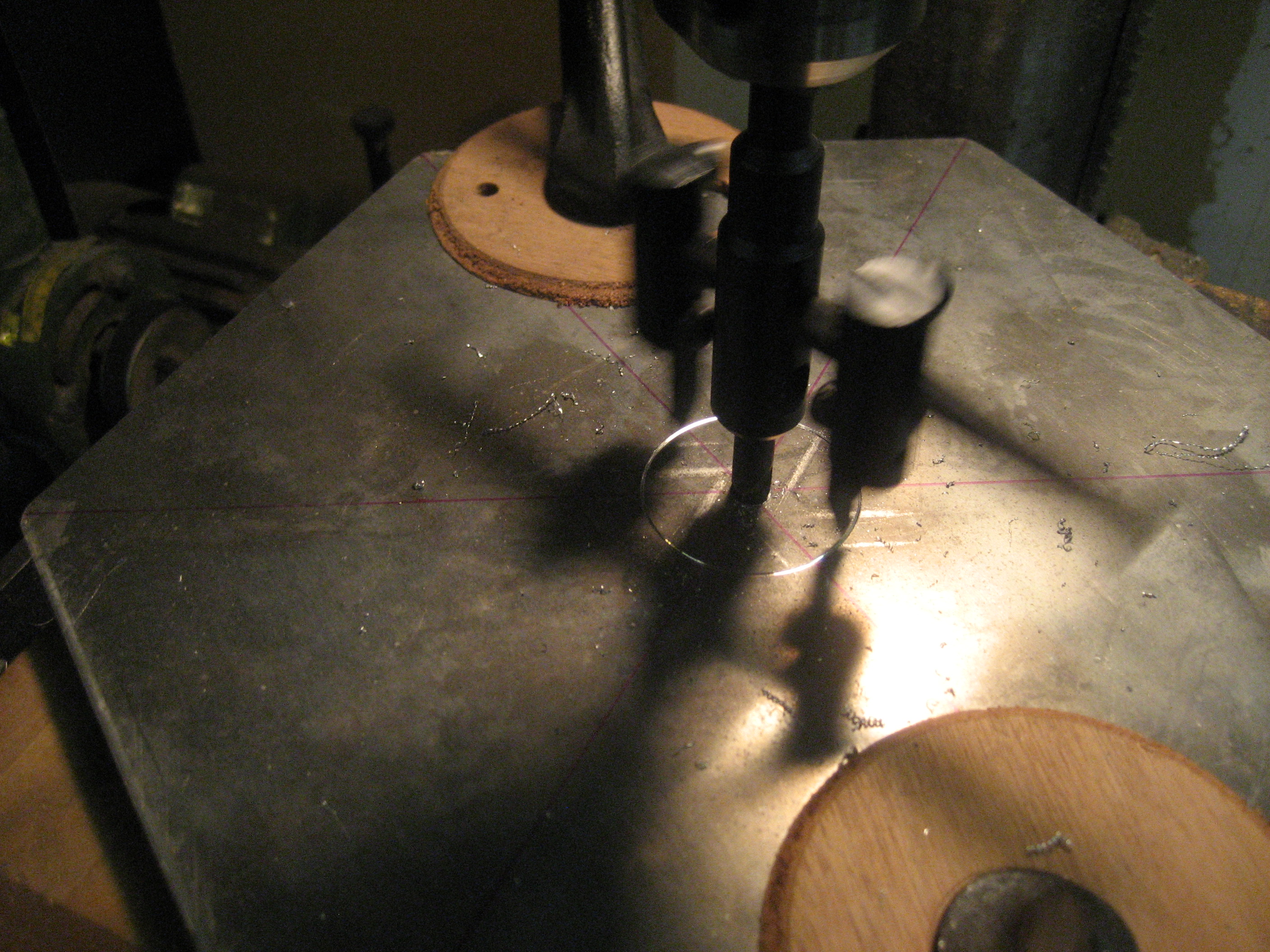
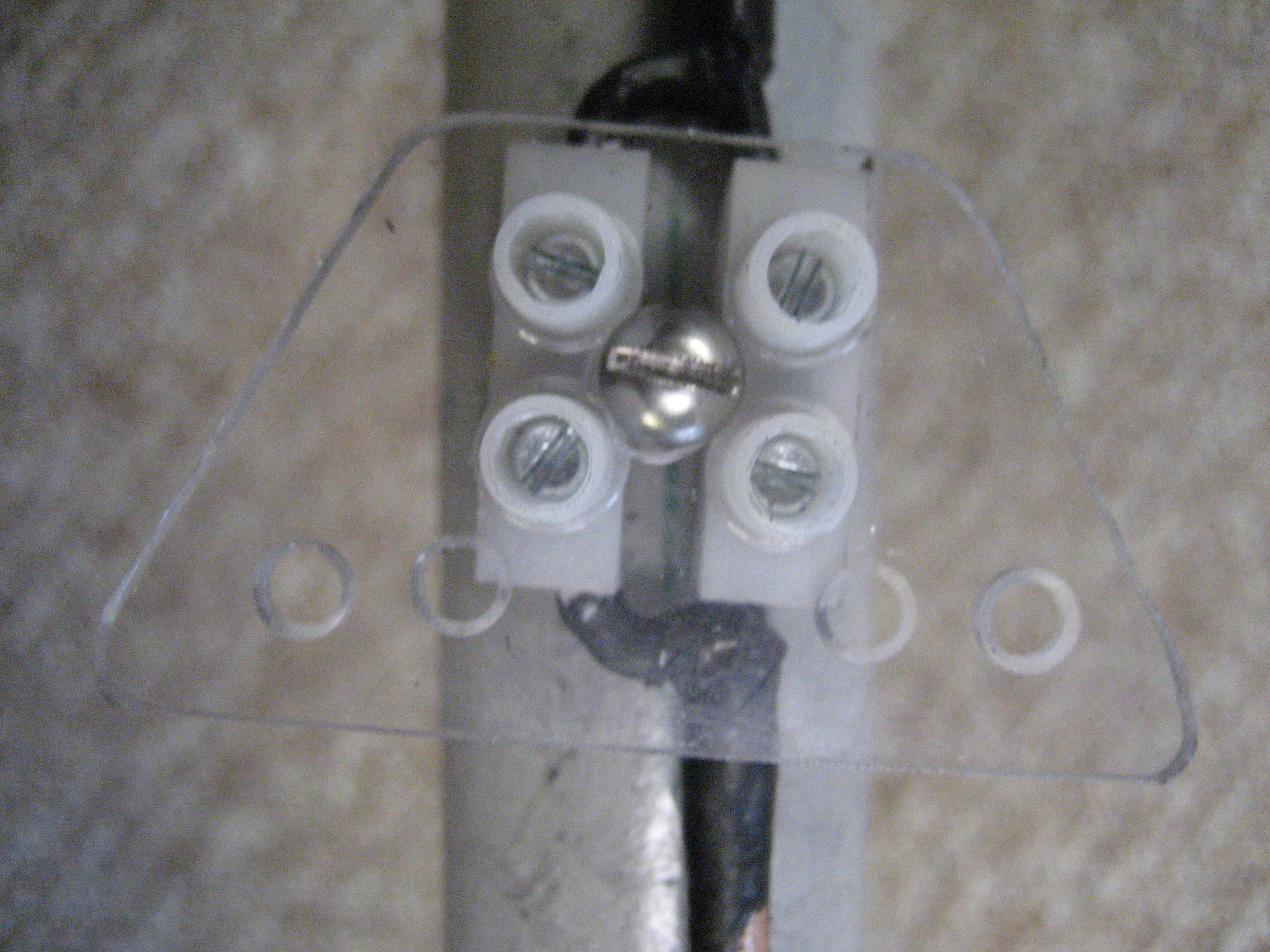
The center post is drilled for feed point terminals.
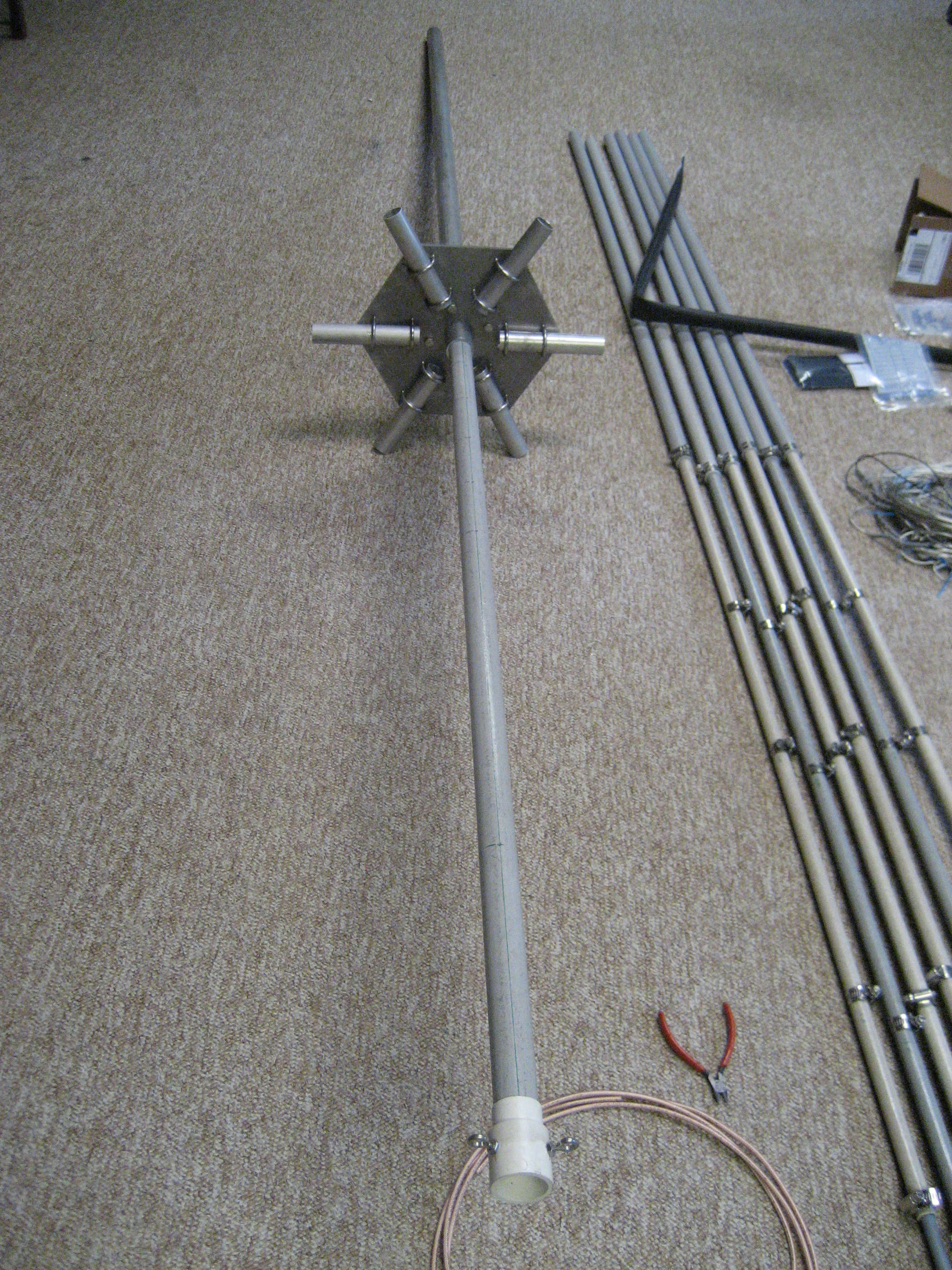
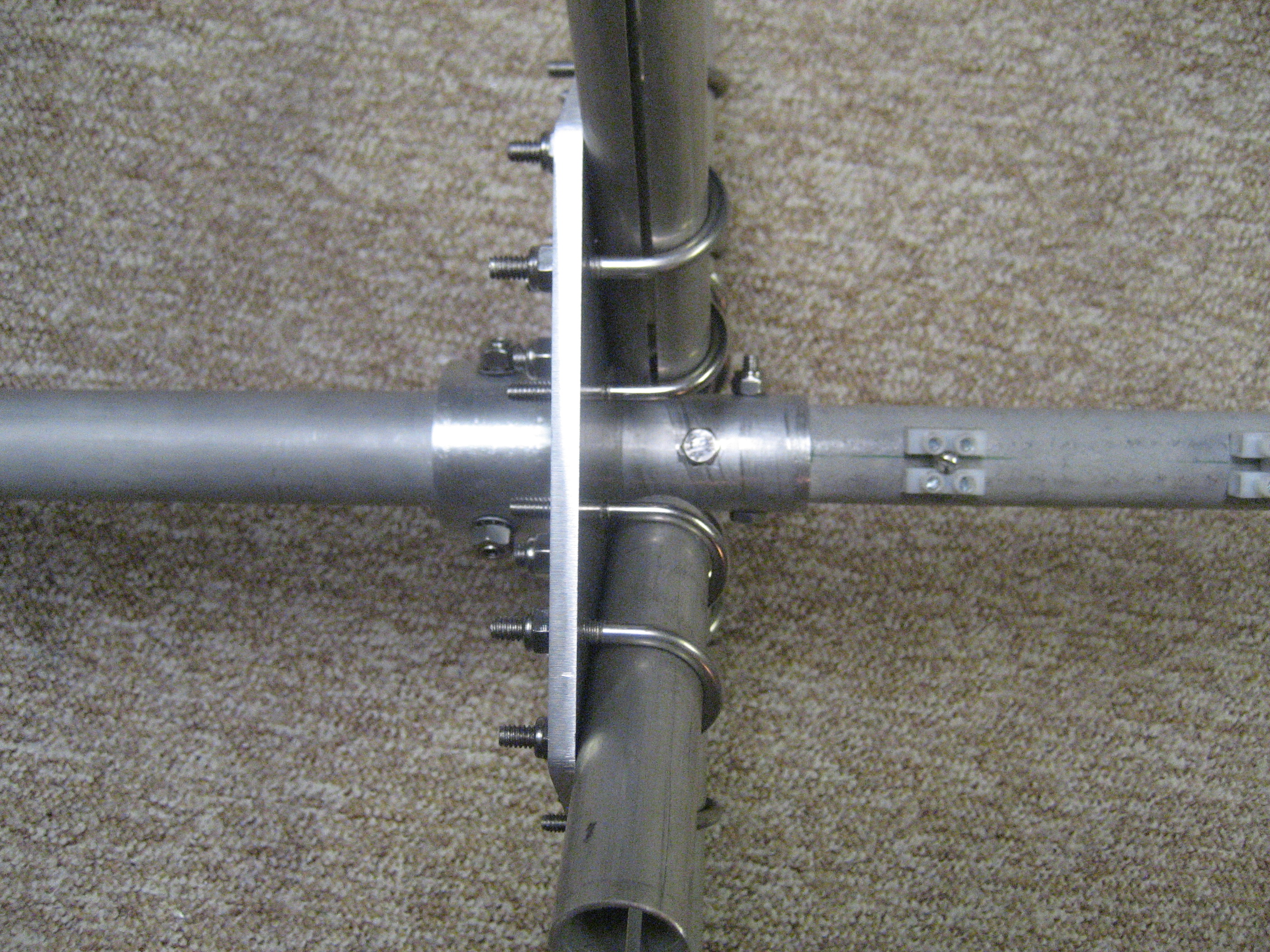
The center post fitted in place.
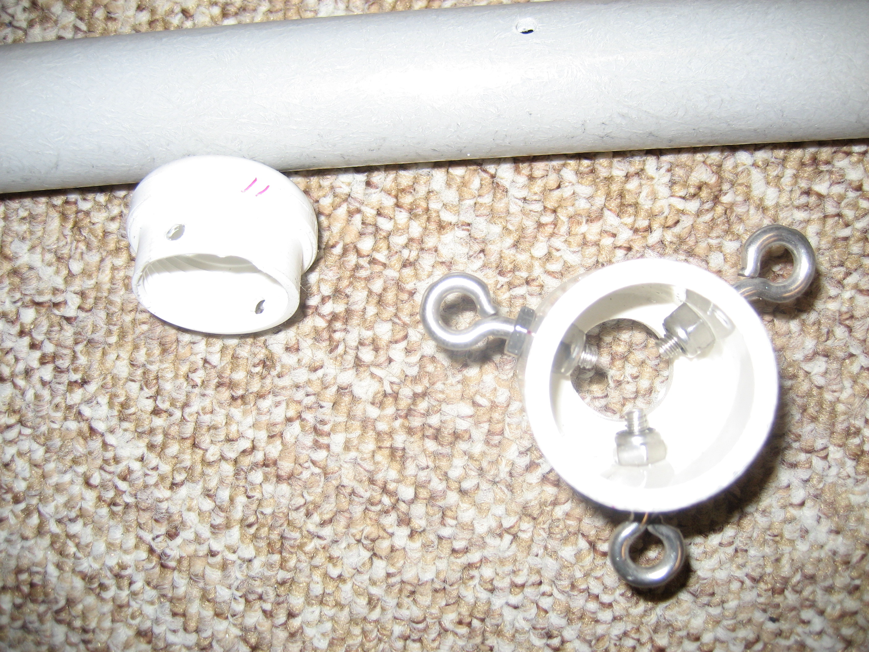
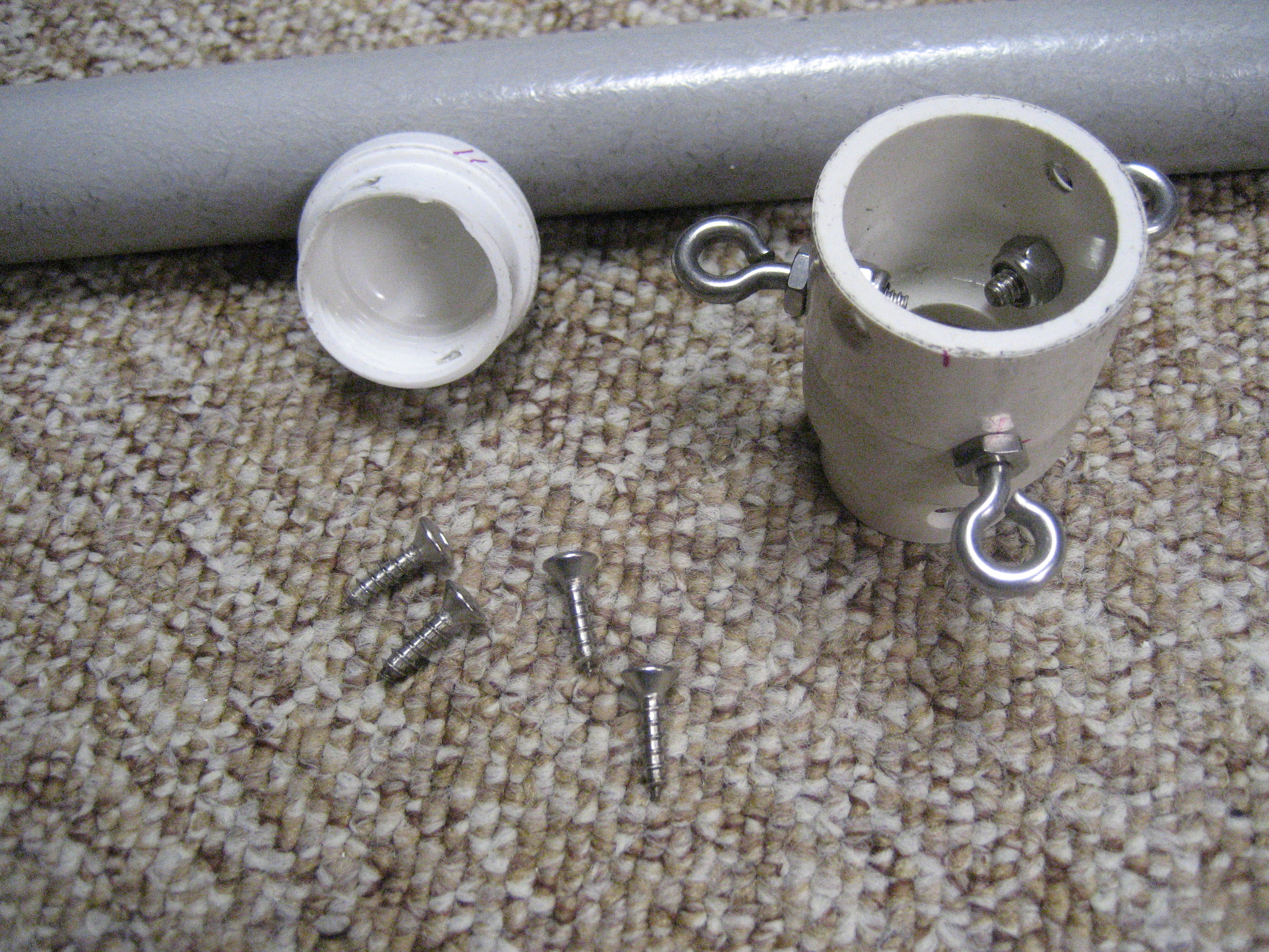
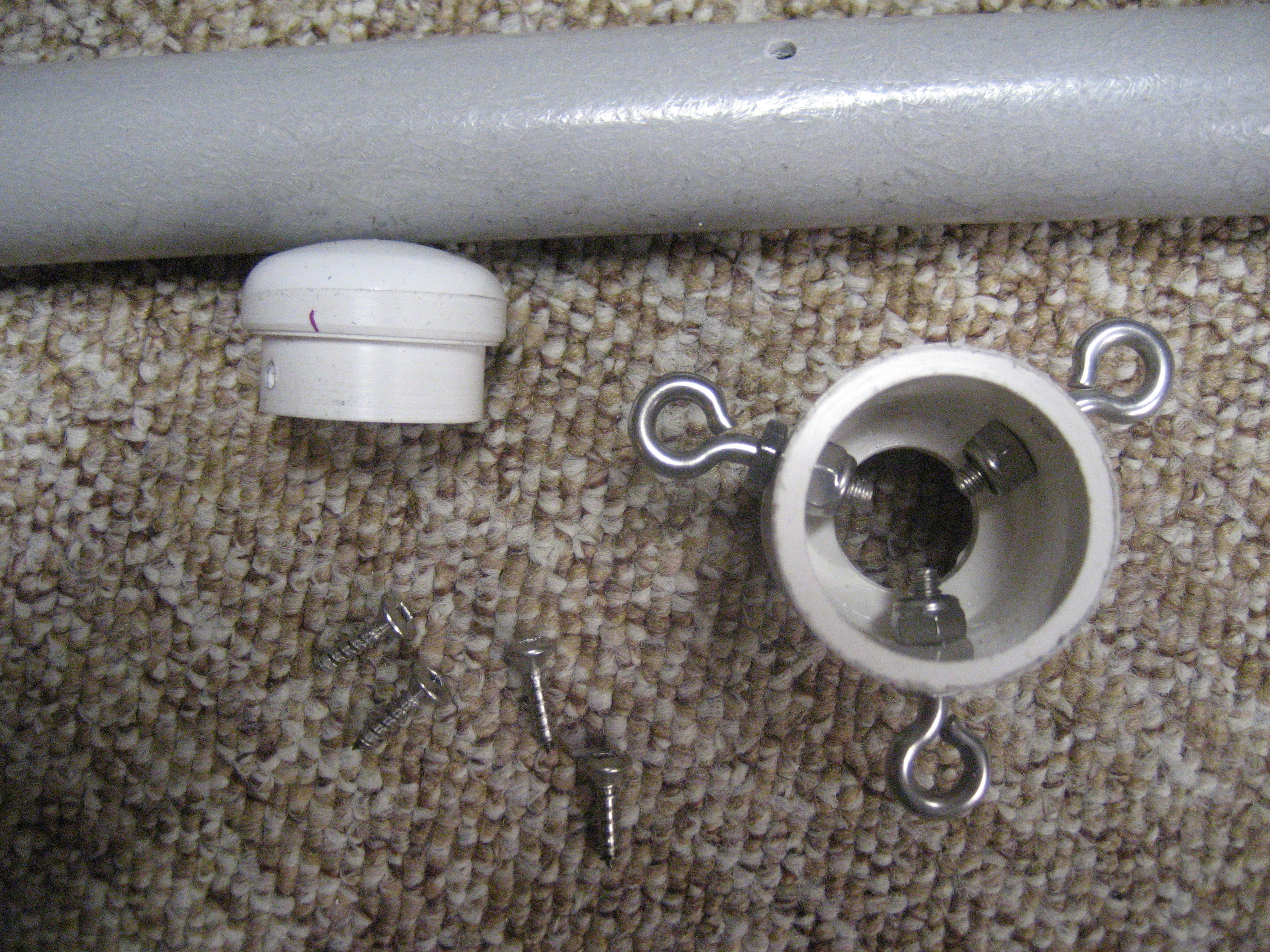
Details of the center post cap. Both white parts are made from pvc fittings with some modifications on a lathe. Tensioning cords will atach to the eye-bolts.
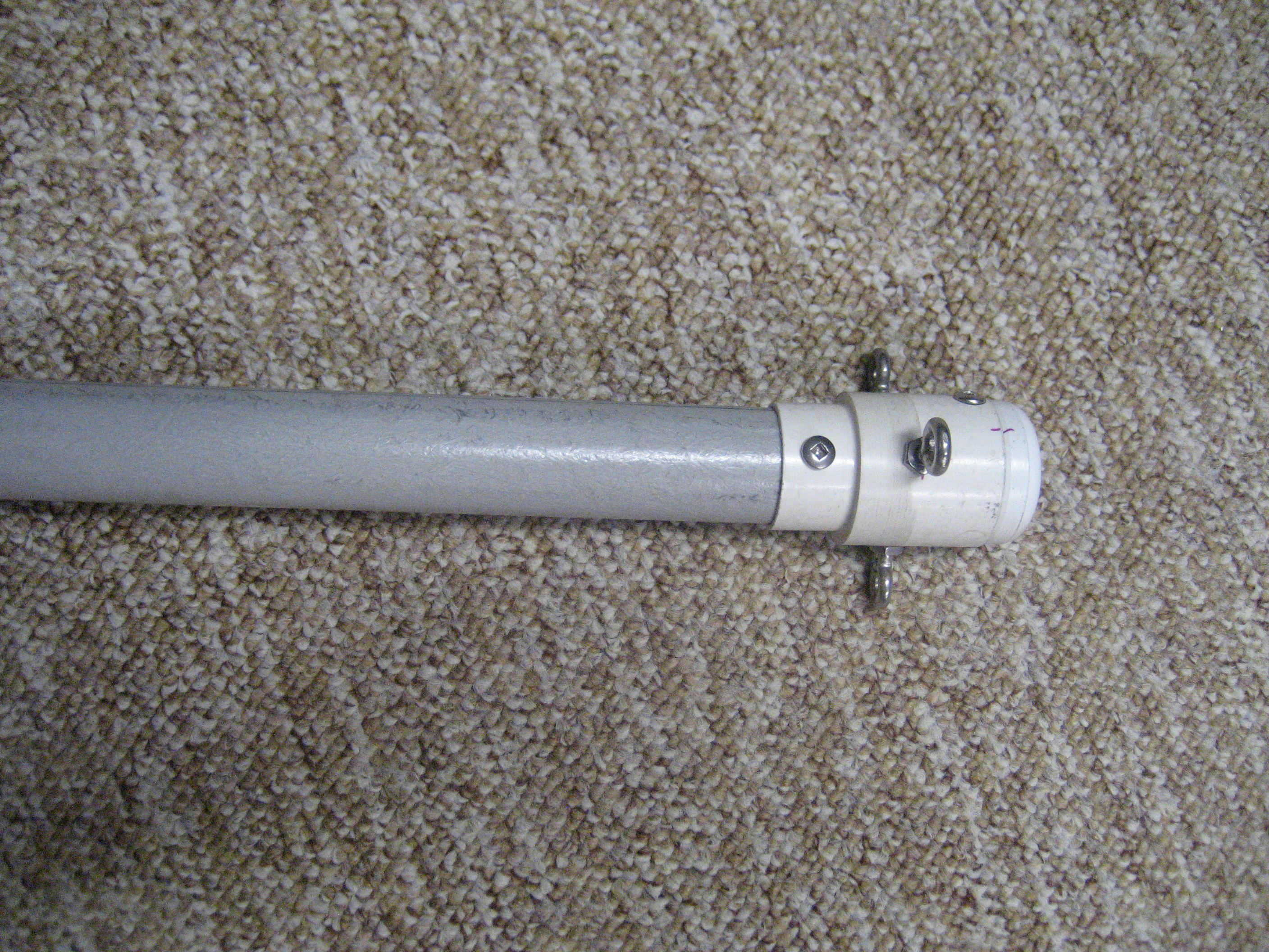
The center-post cap in place.
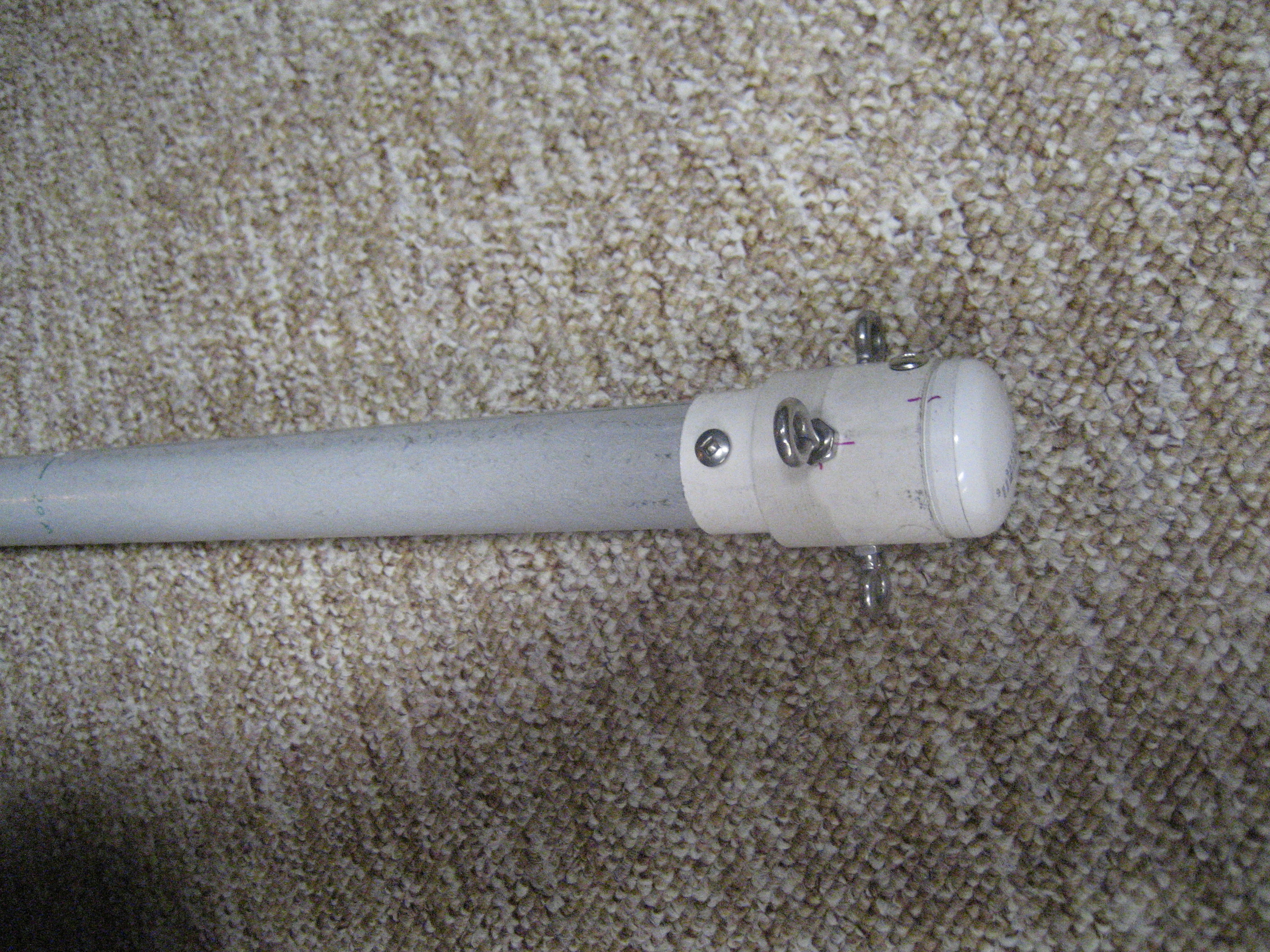
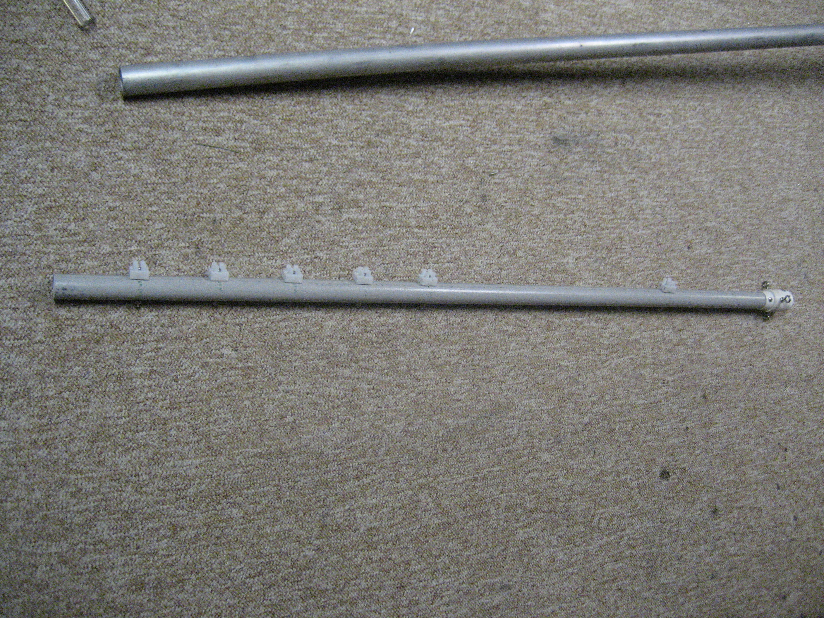
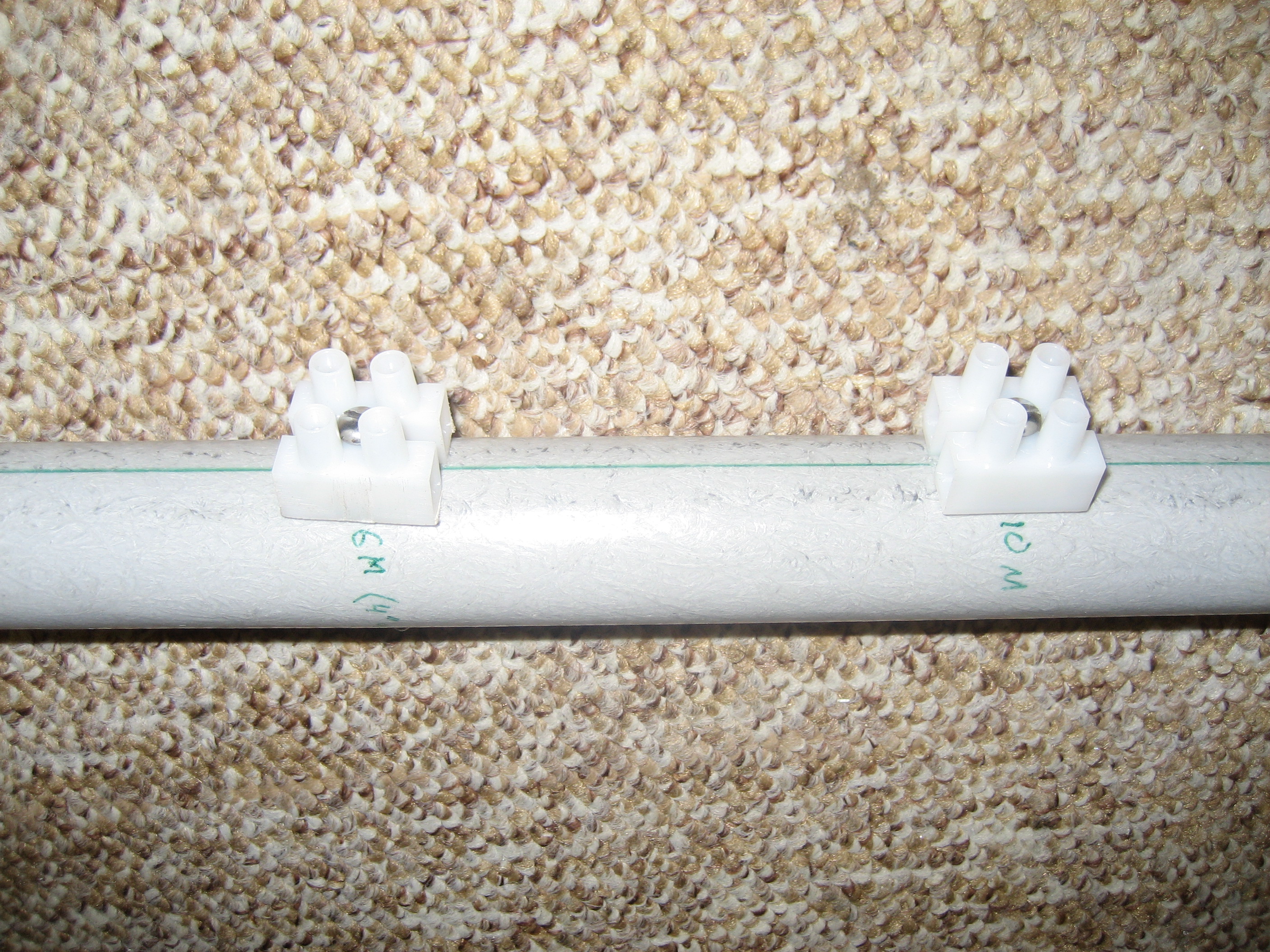
The mostly-assembled center post. The screw terminal connectors are modified from a Radio Shack jumbo-sized terminal strip (#274-677)
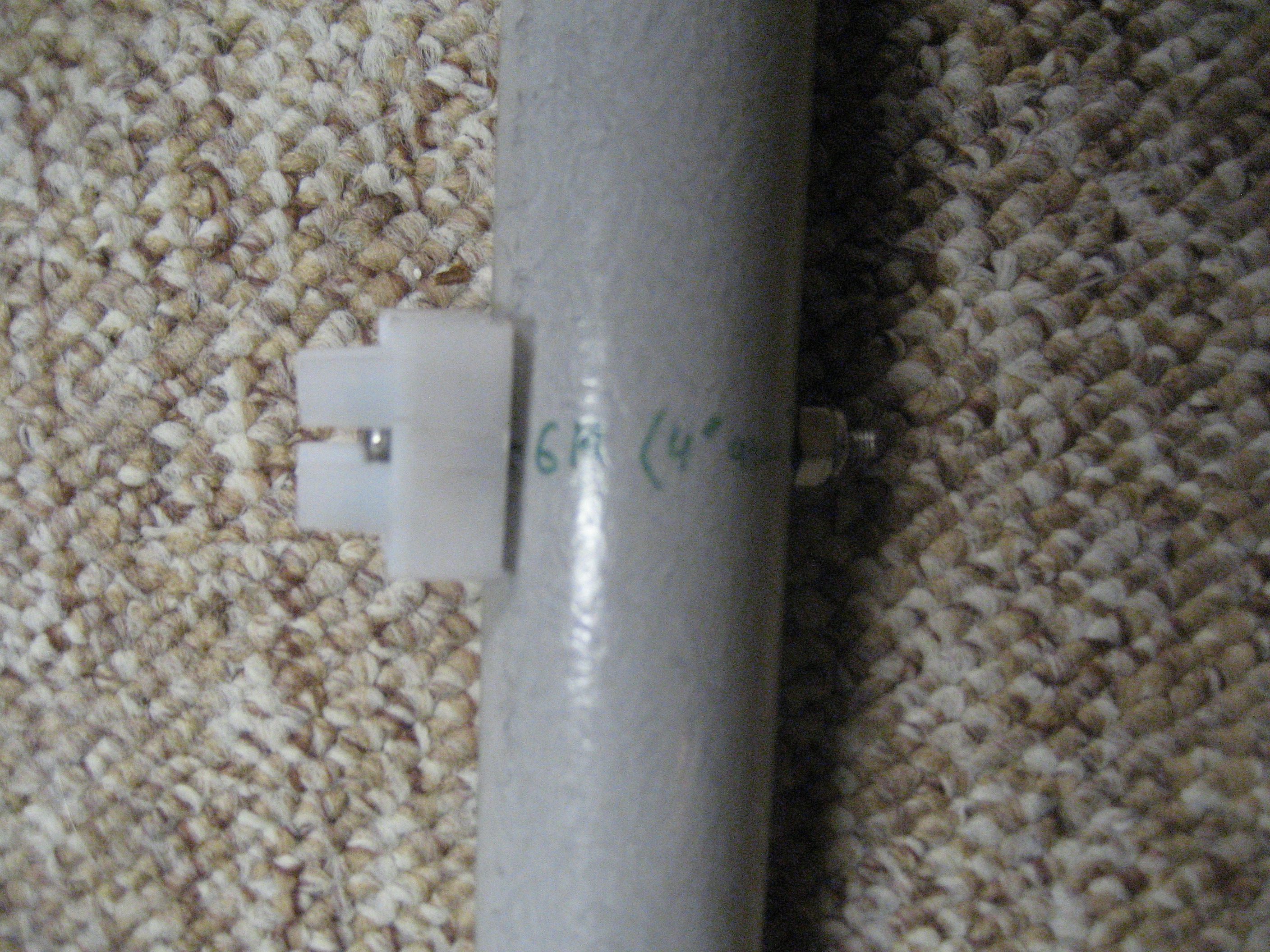
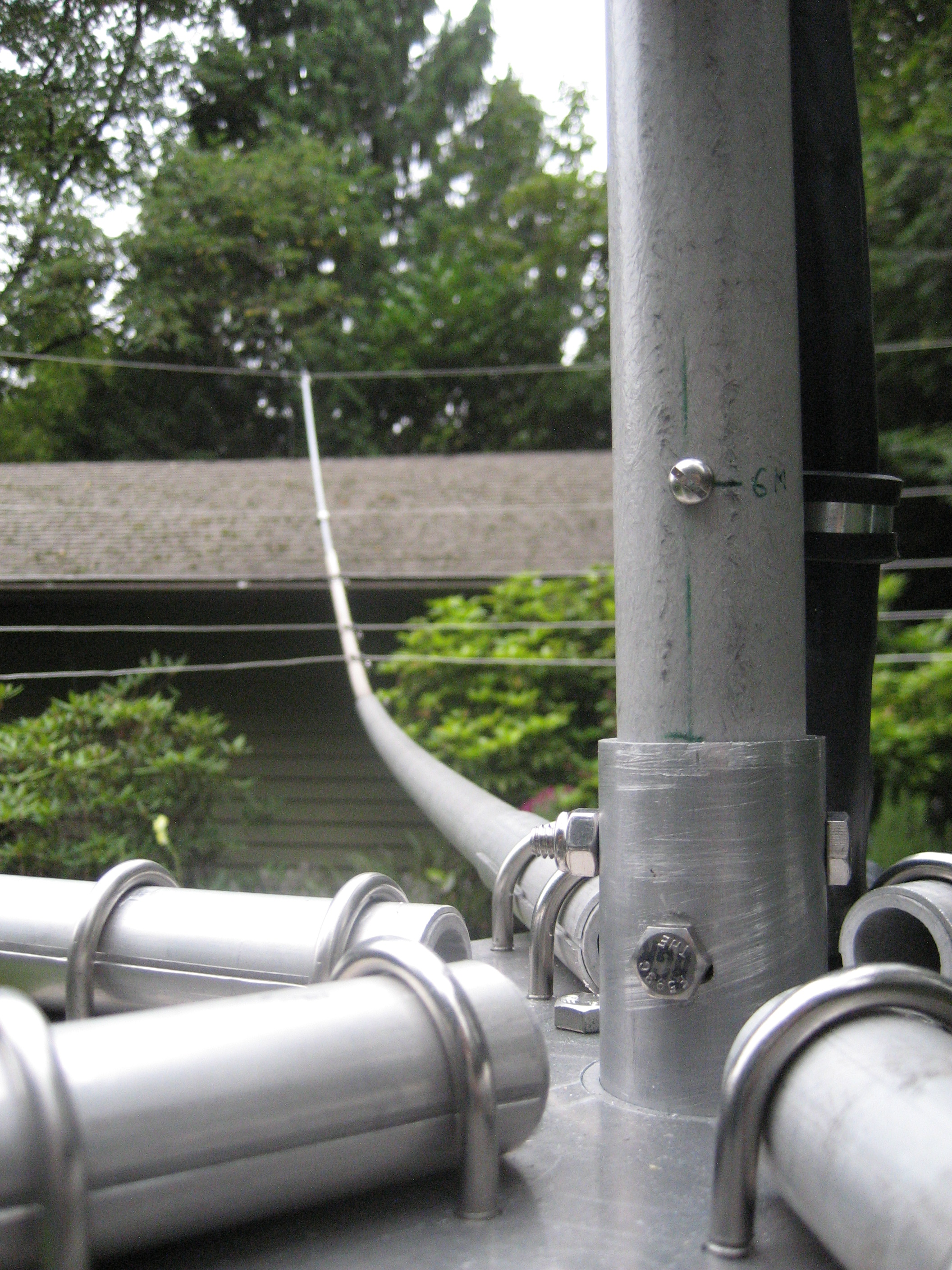
I added capabilities for 6 meters, but I didn't use it. I have other plans for six.
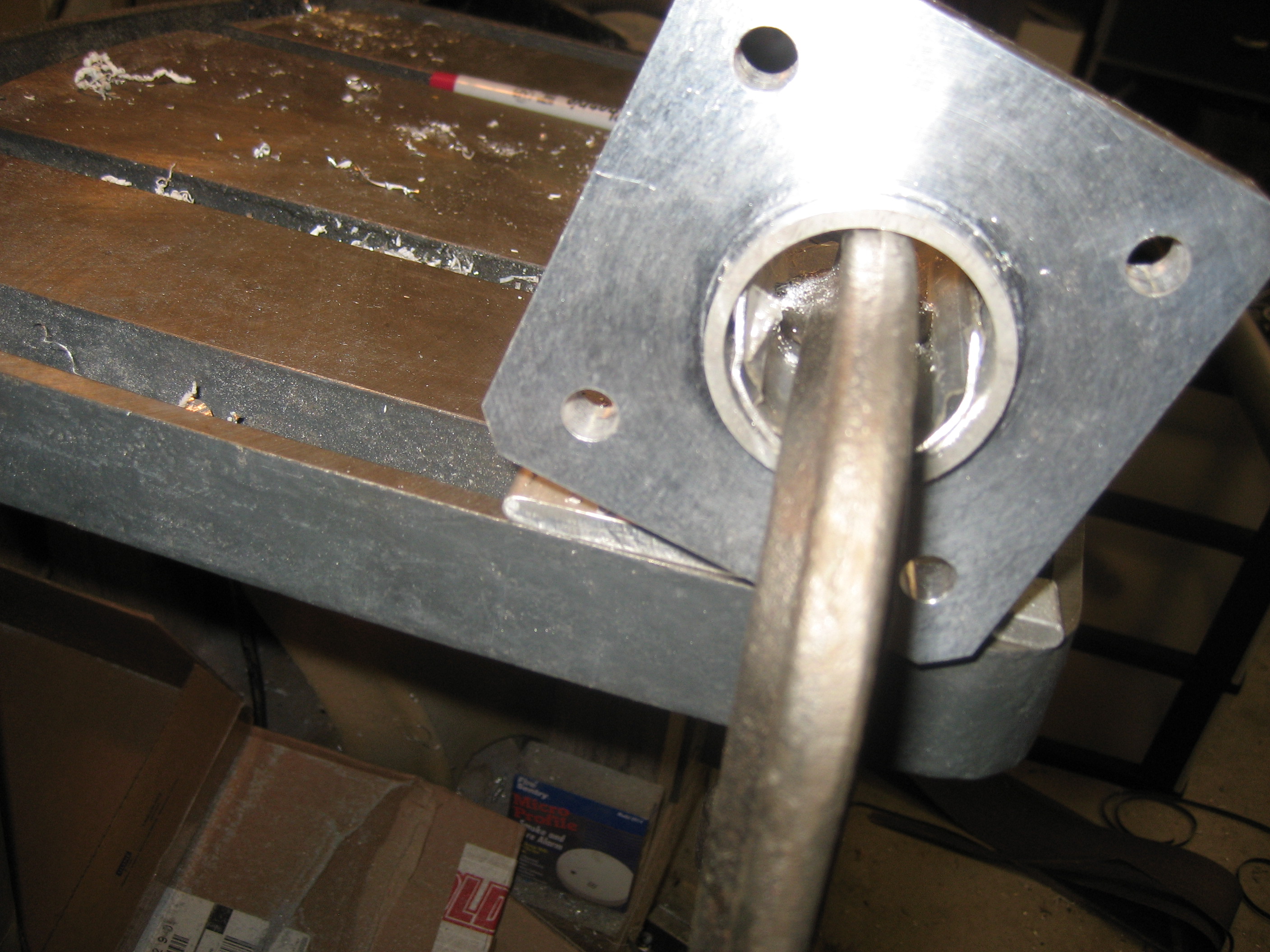
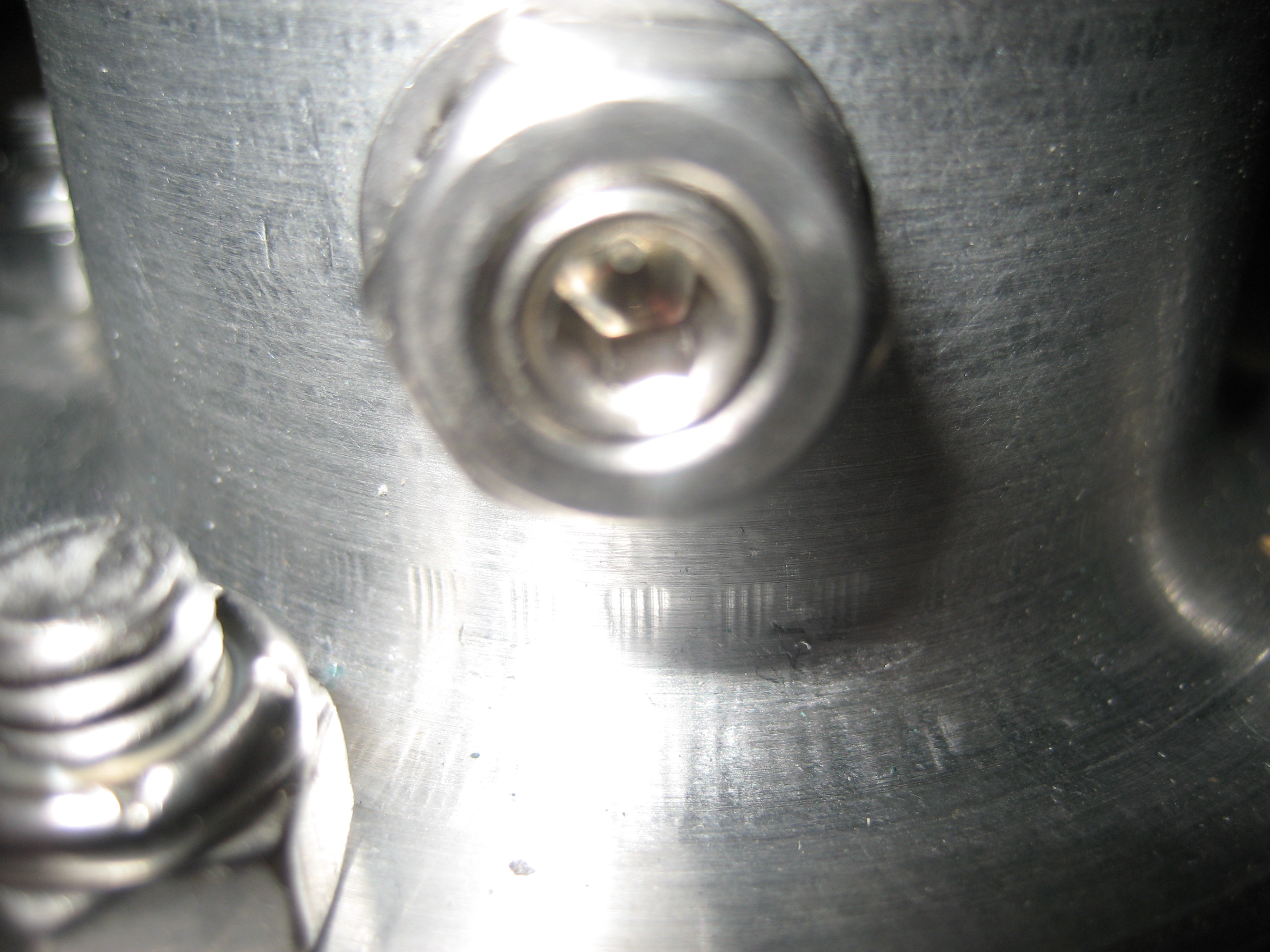
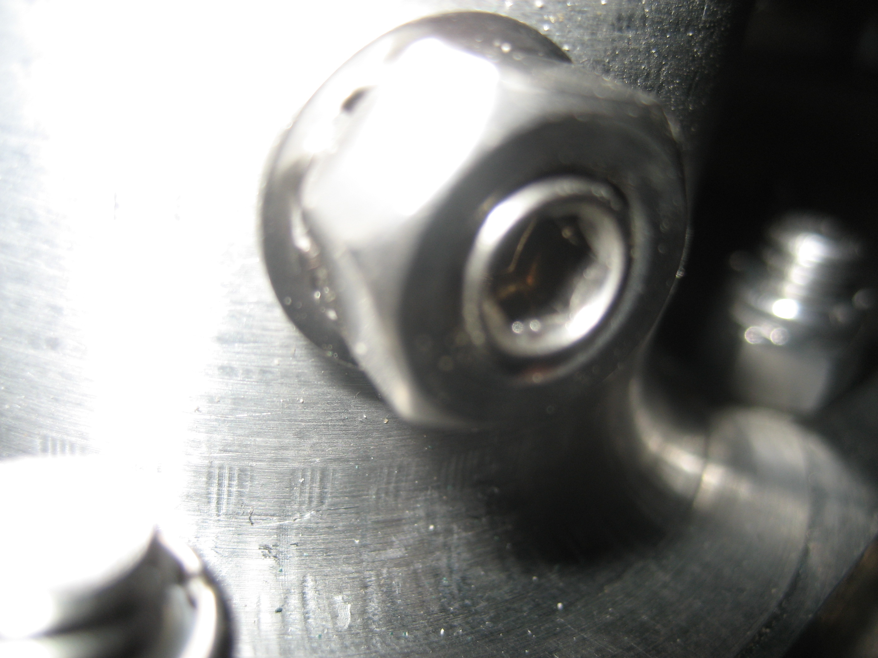
The hub is drilled for set screws that will hold the metal mast.
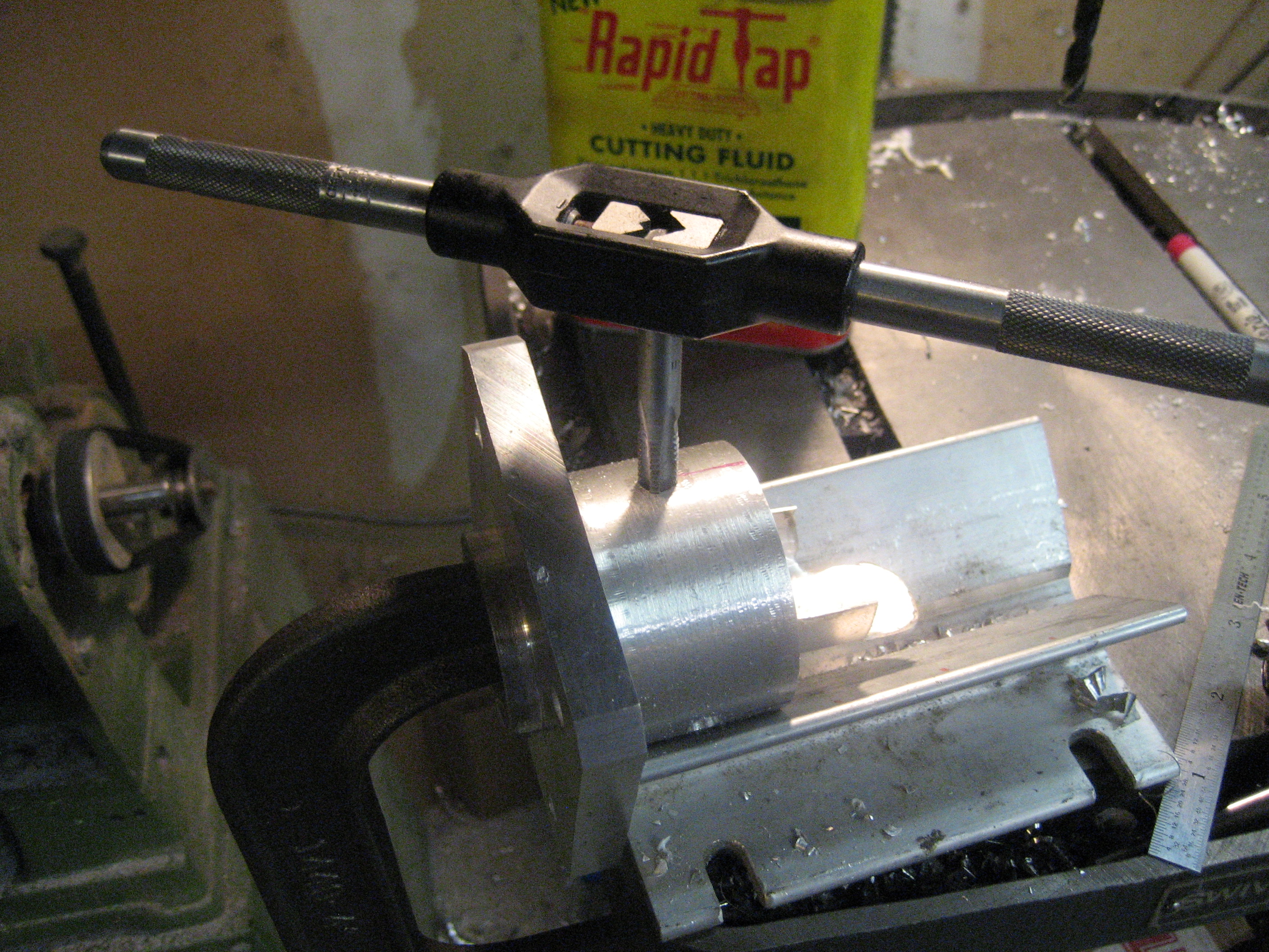
And tapped.
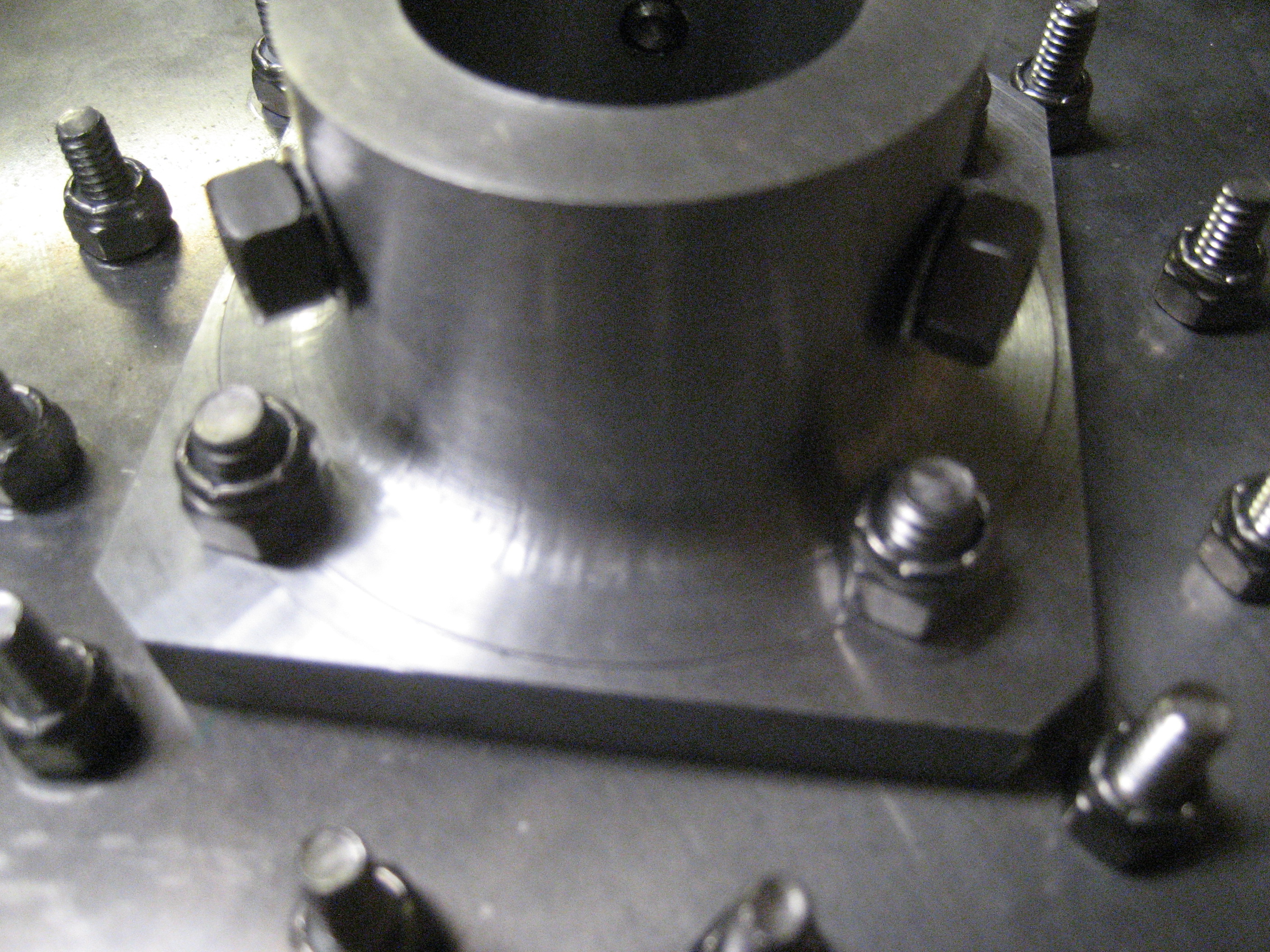
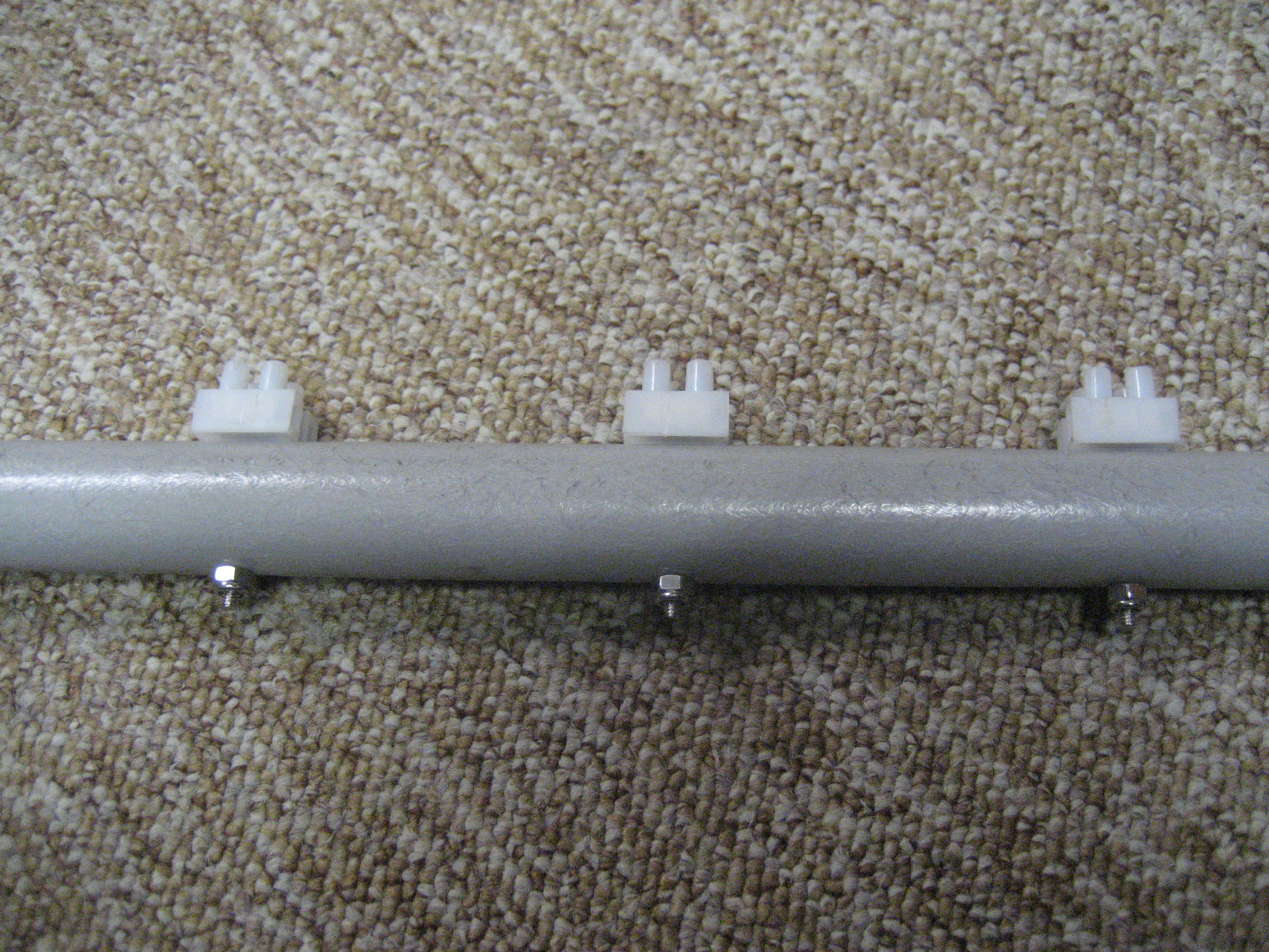
Set screws in place with locking nuts.
The toroid balun.
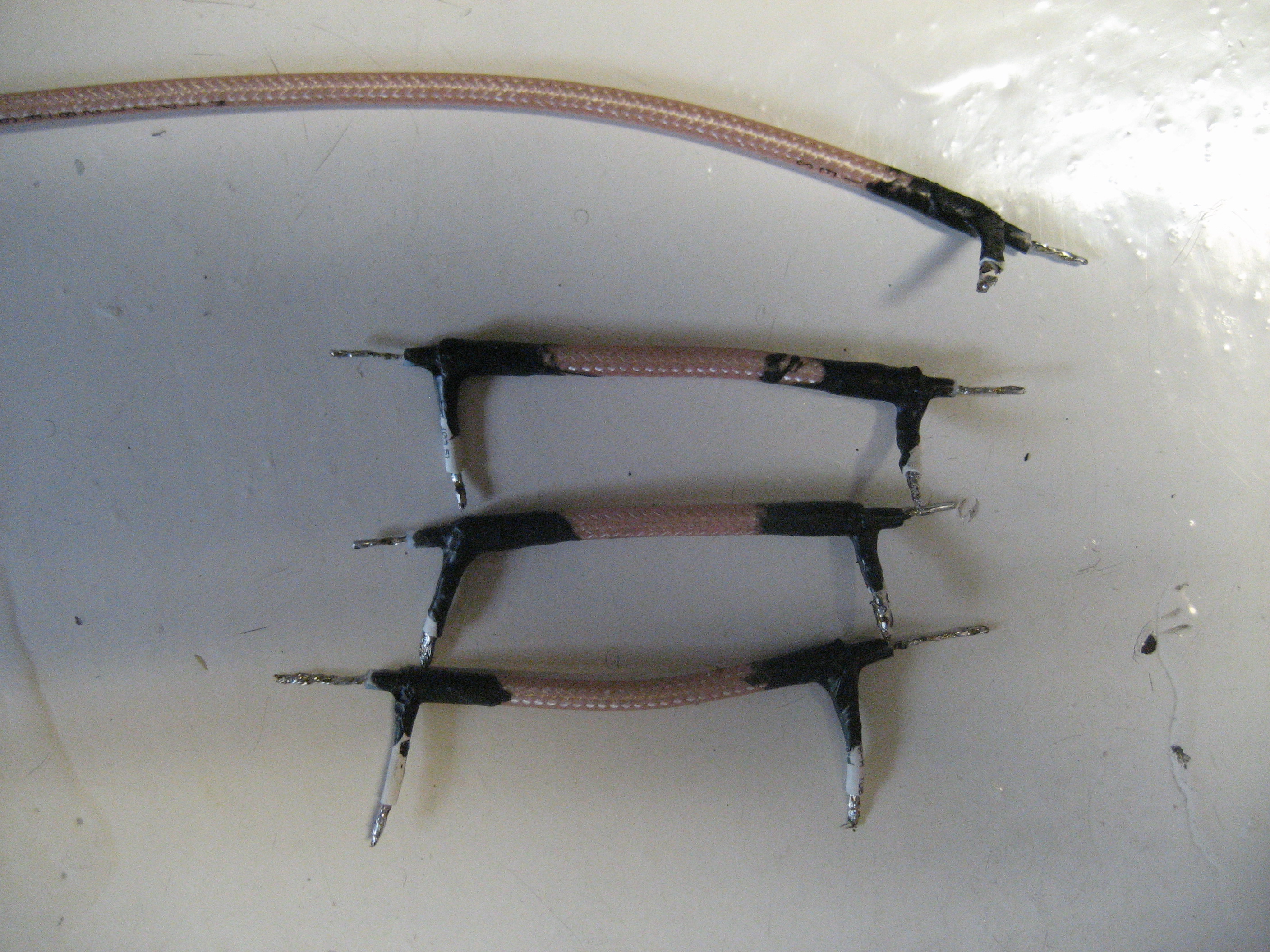
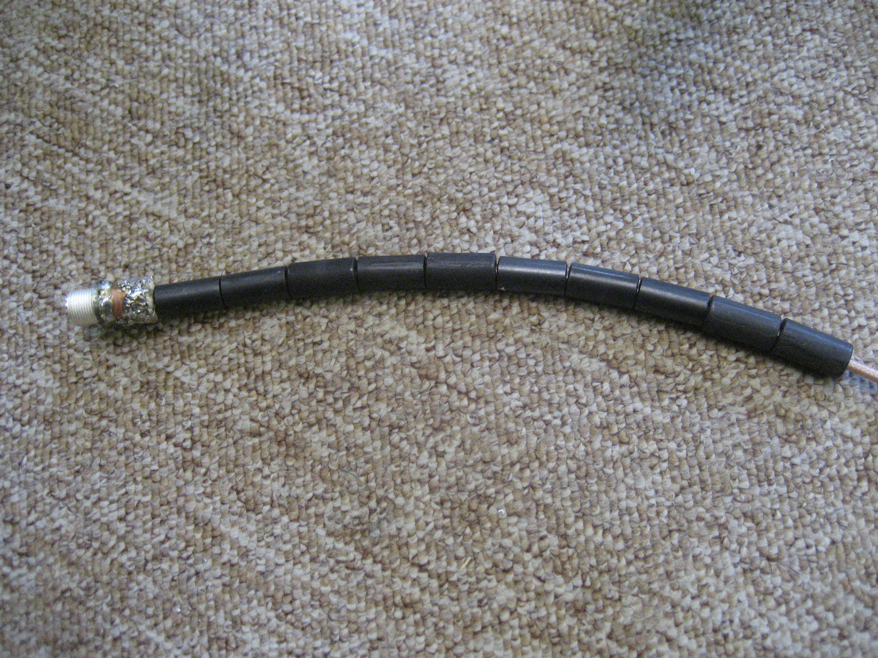
The inter-element feed pieces. The coax for the antenna is a scrap of RG-400 left over from an airplane project.
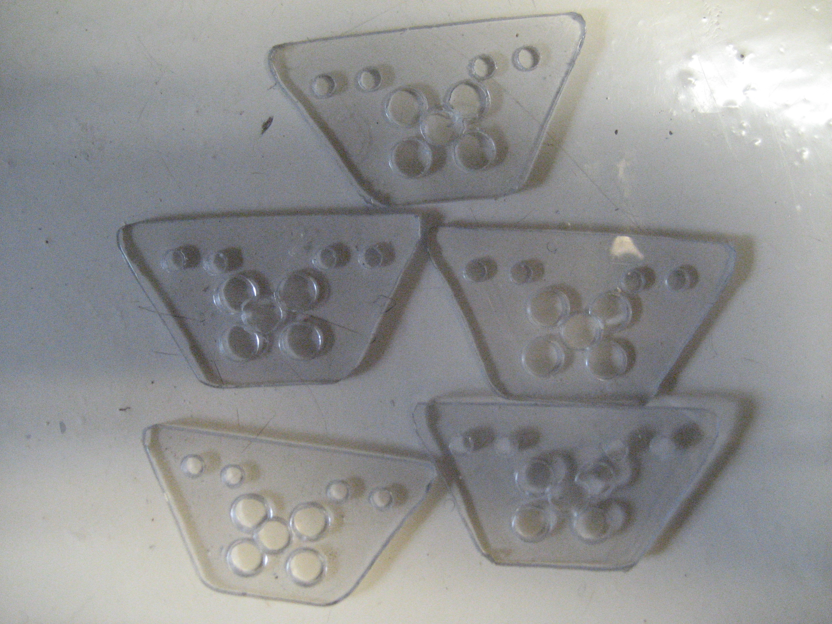
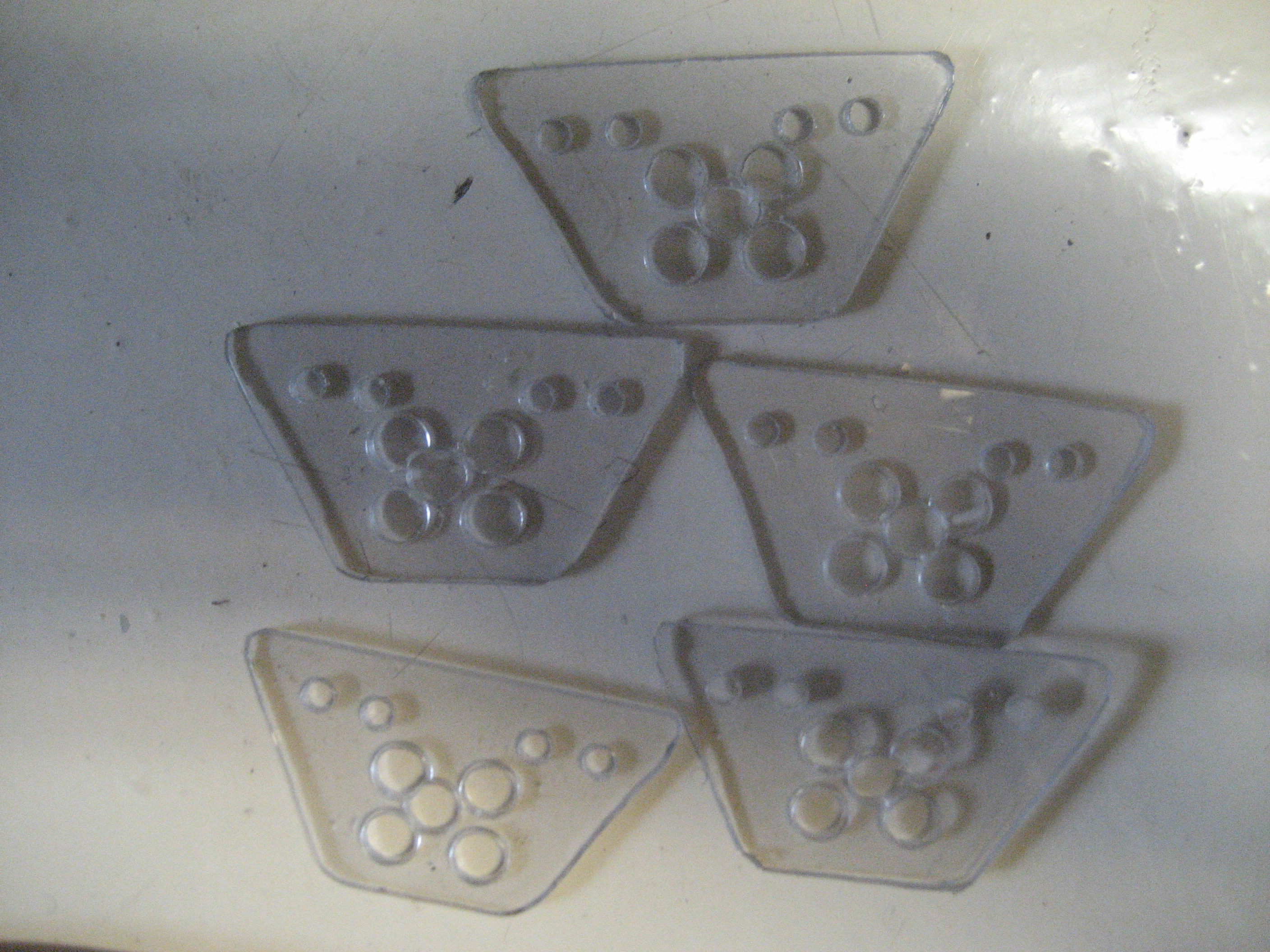
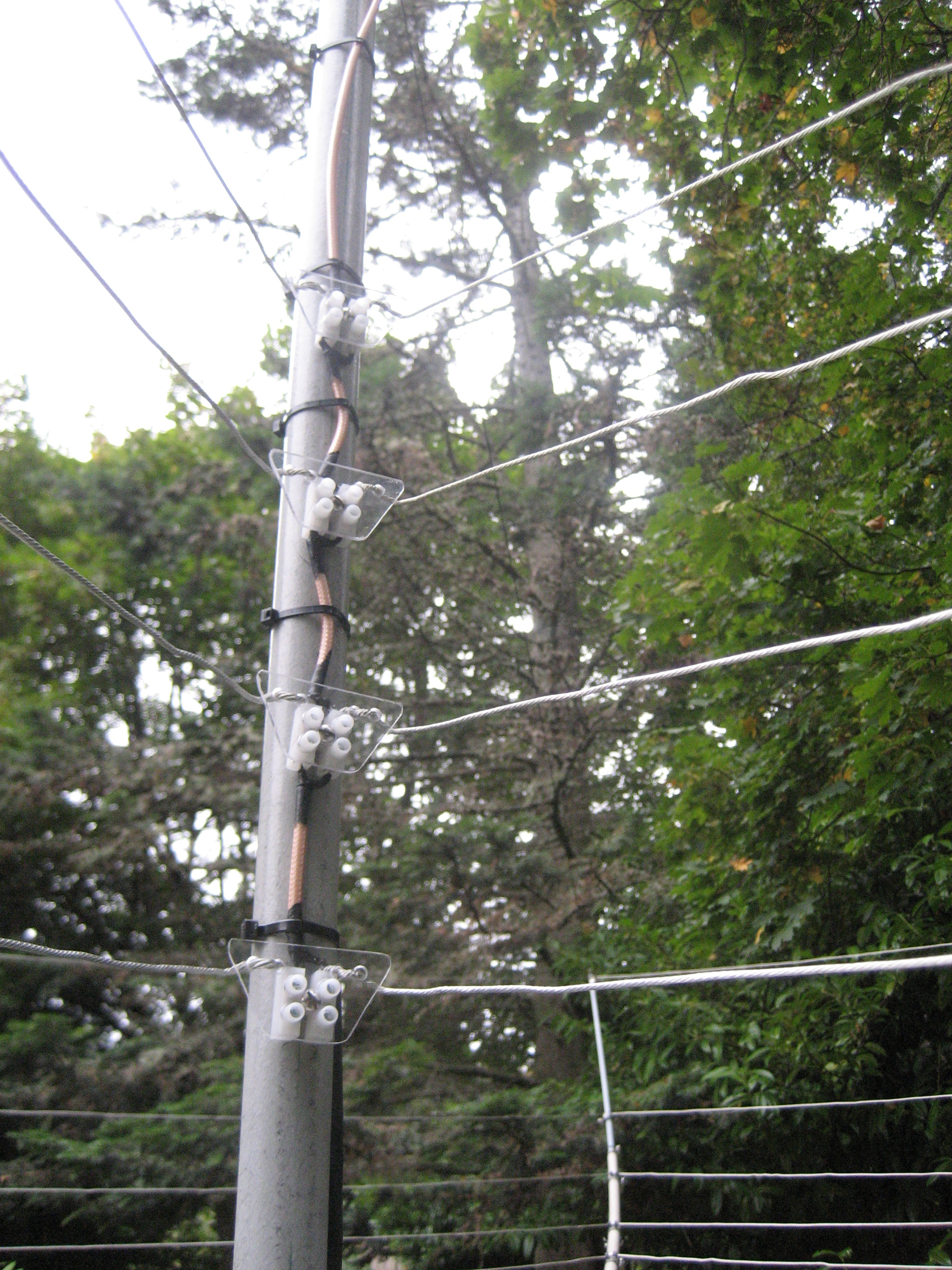
Strain relief for the driven elements are made from Lexan.
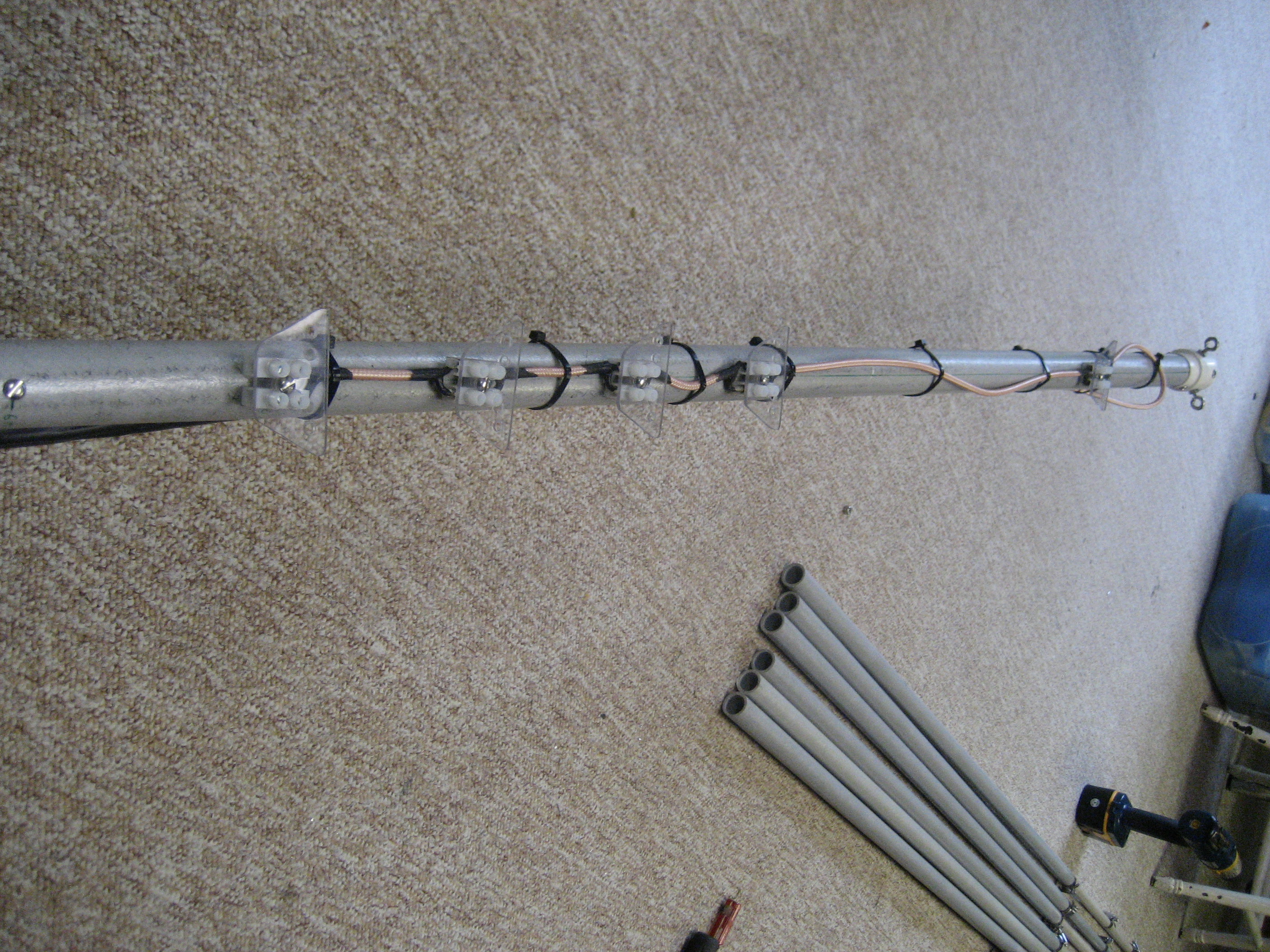
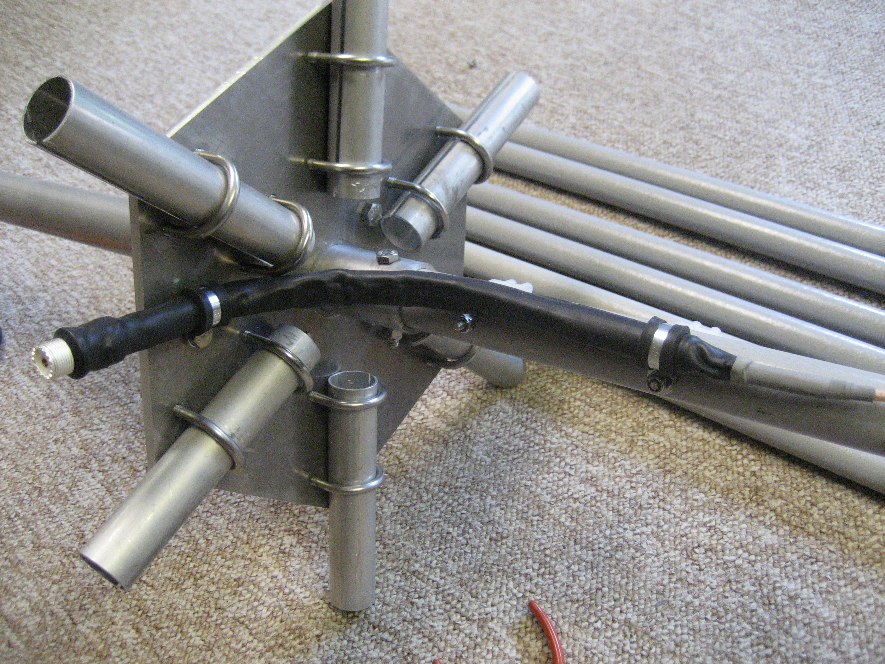
Strain relief and coax in place. The black stuff is Liquid Tape.
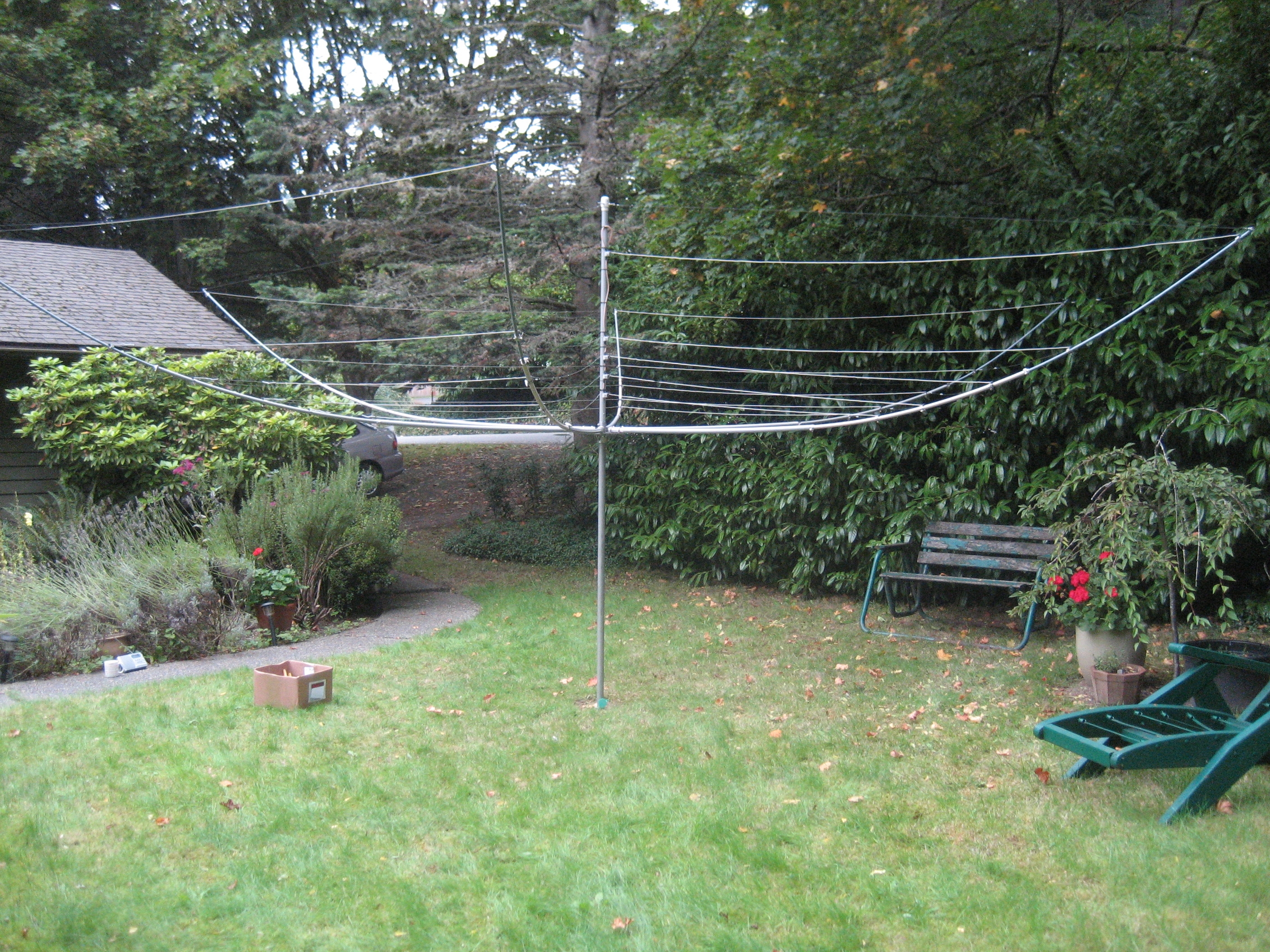
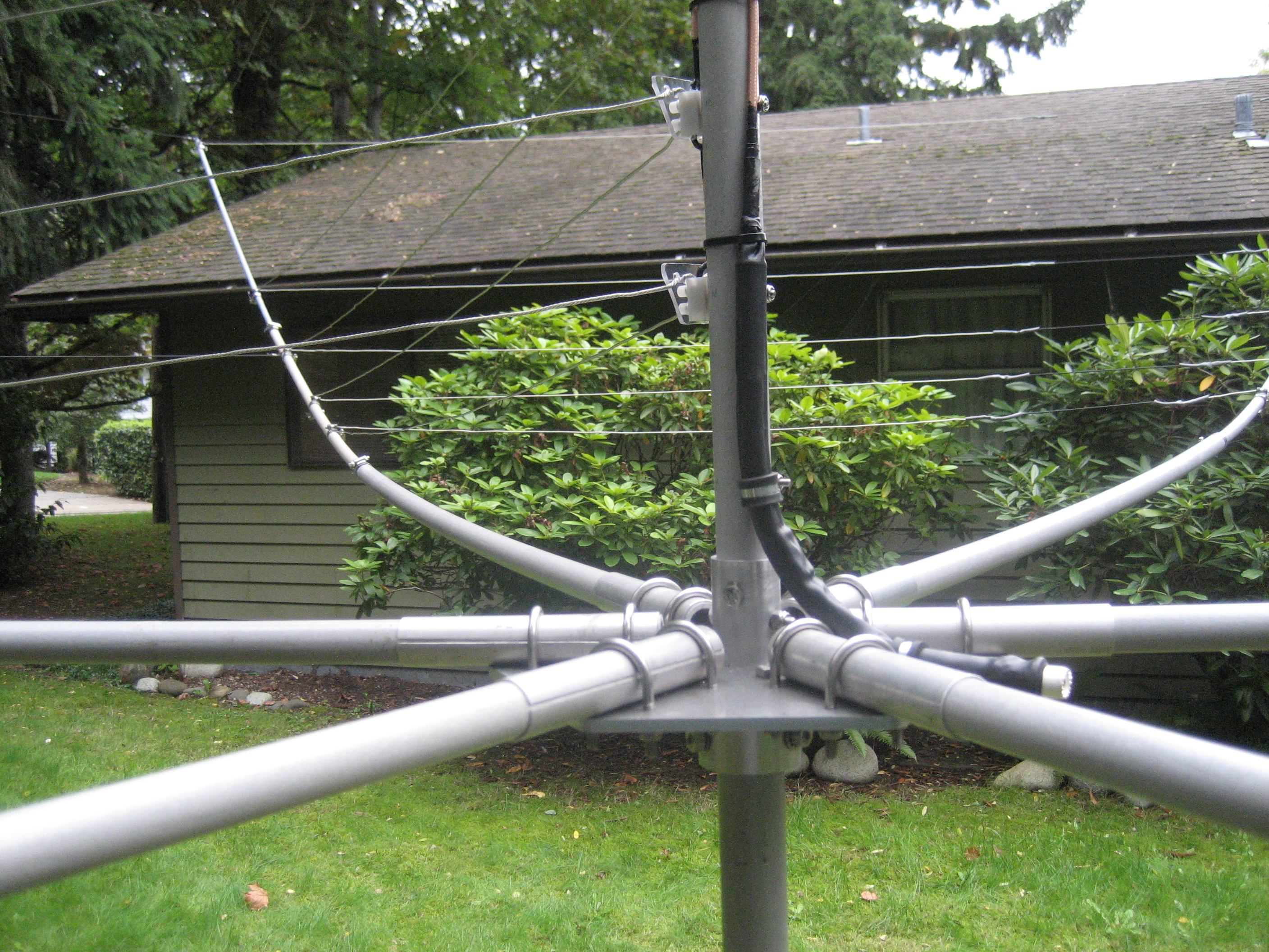
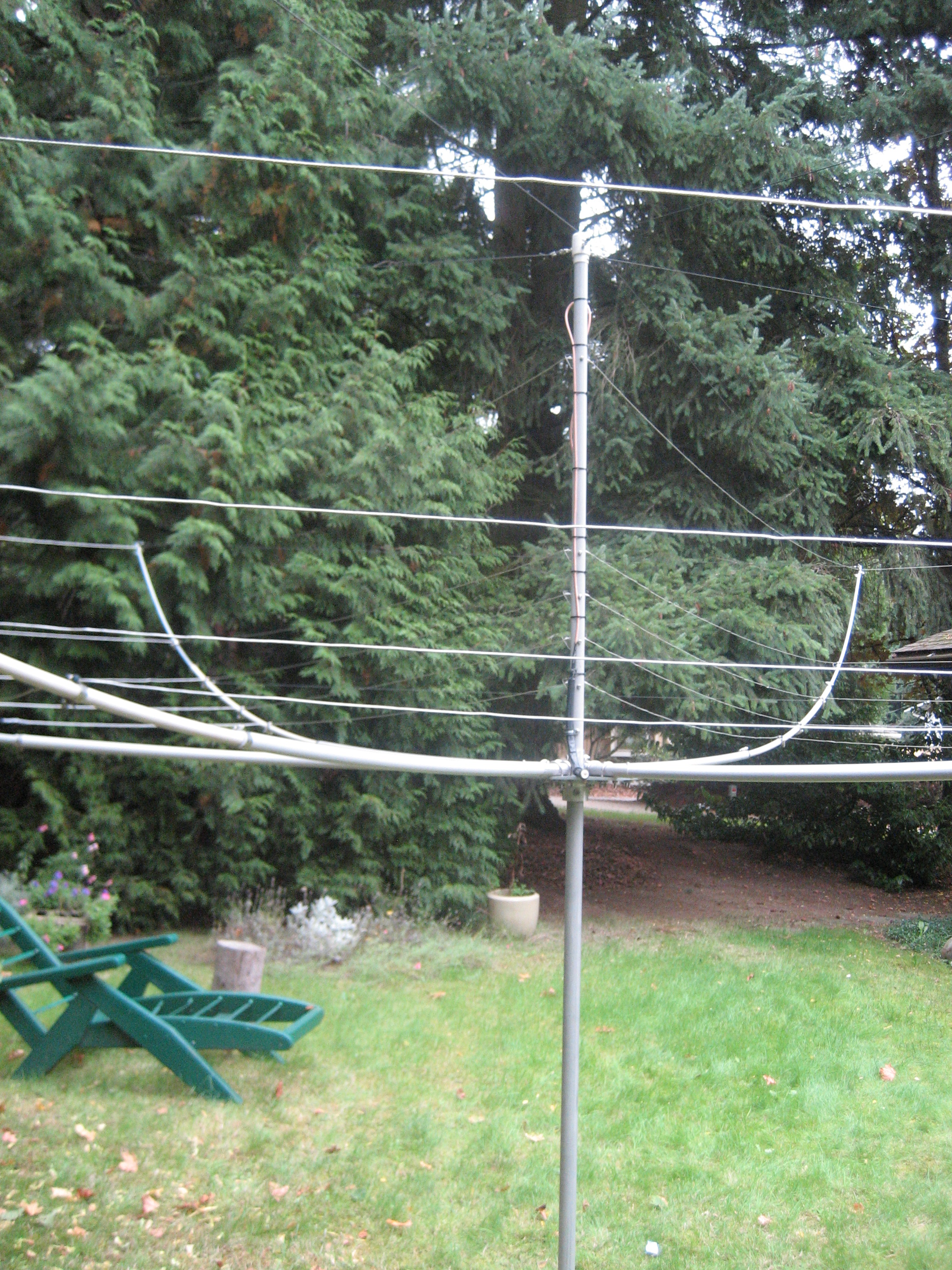
The assembled antenna in my back yard. There is a clothes-line post hole in the ground. Very handy!
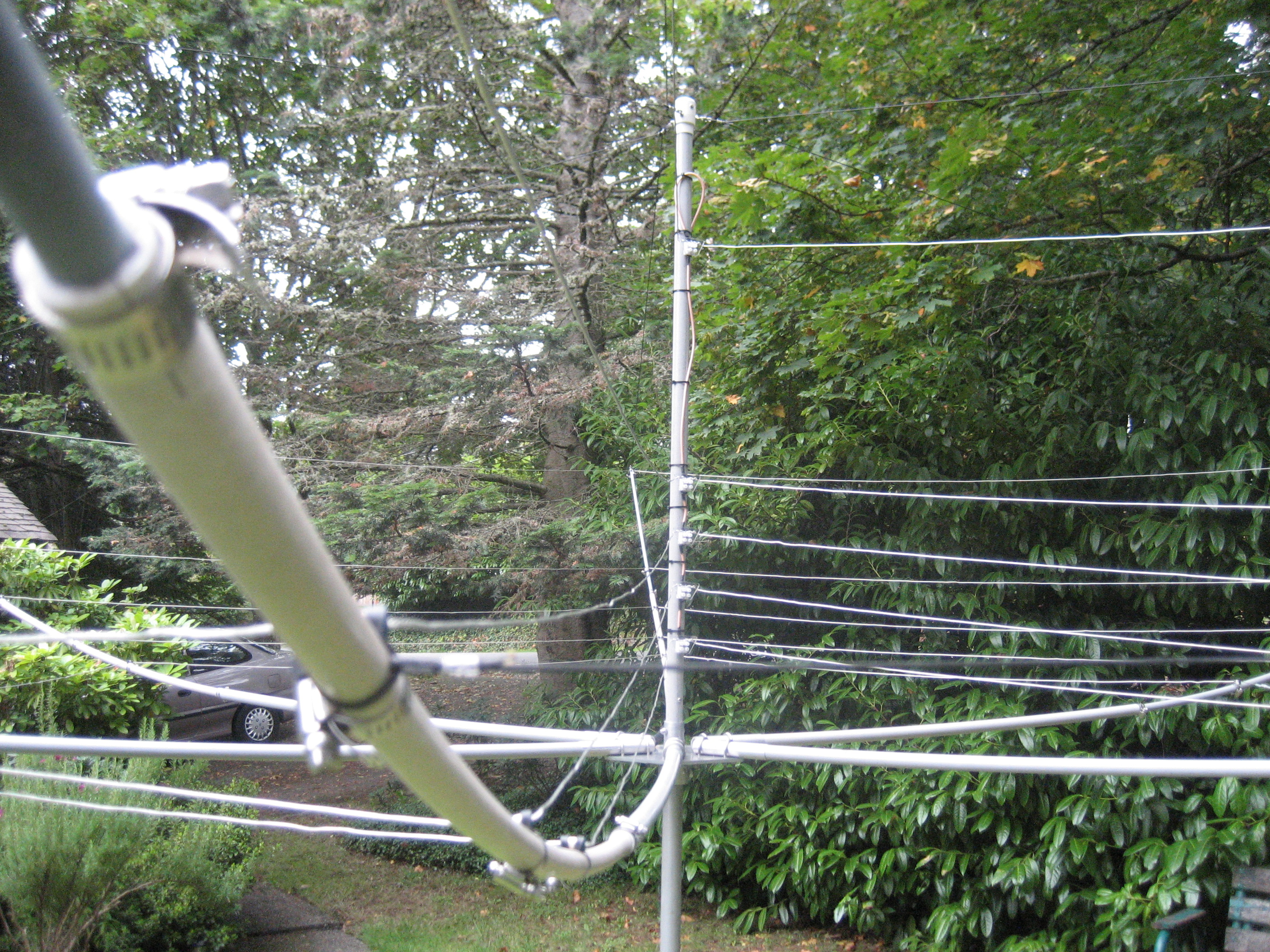
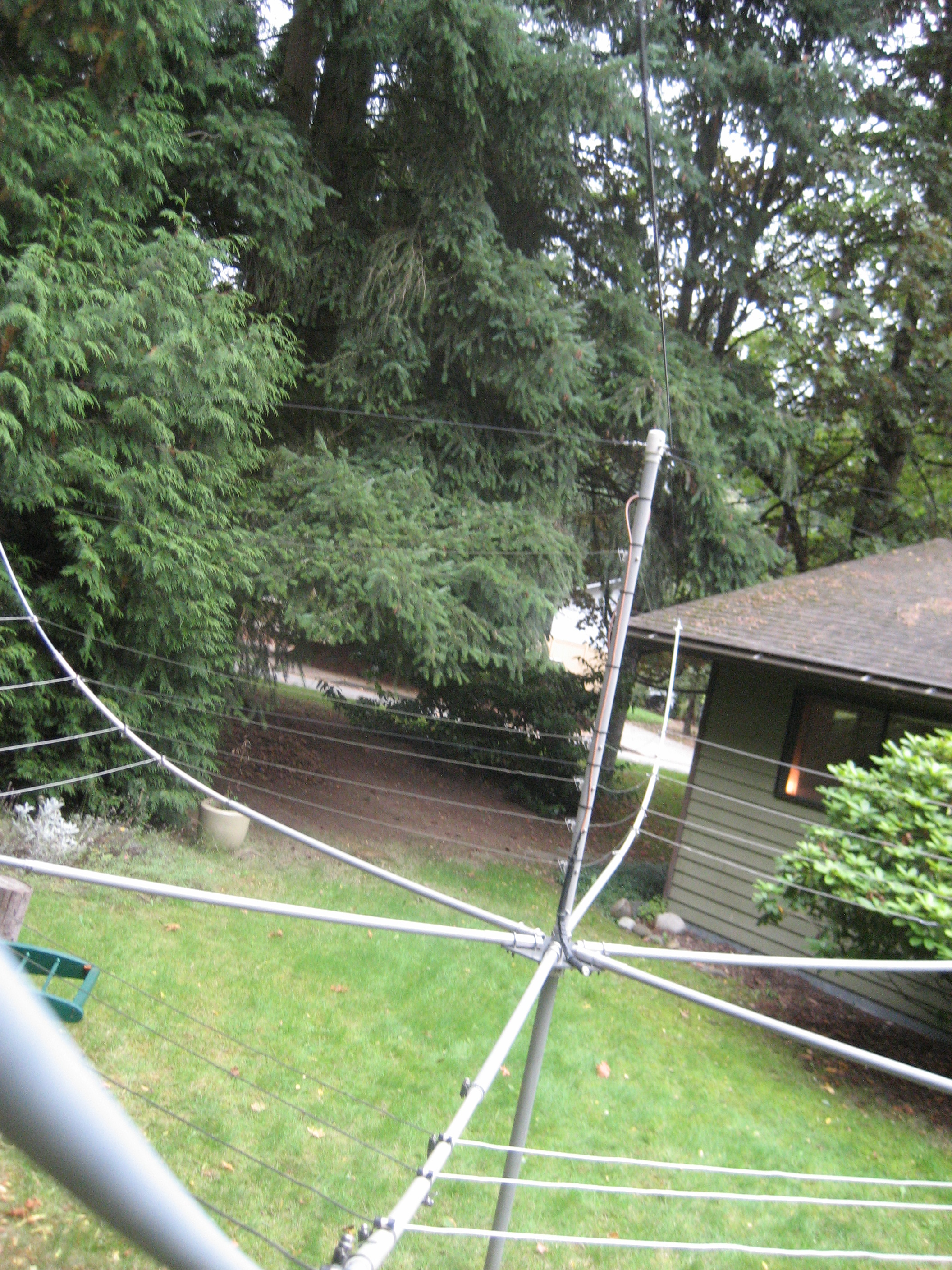
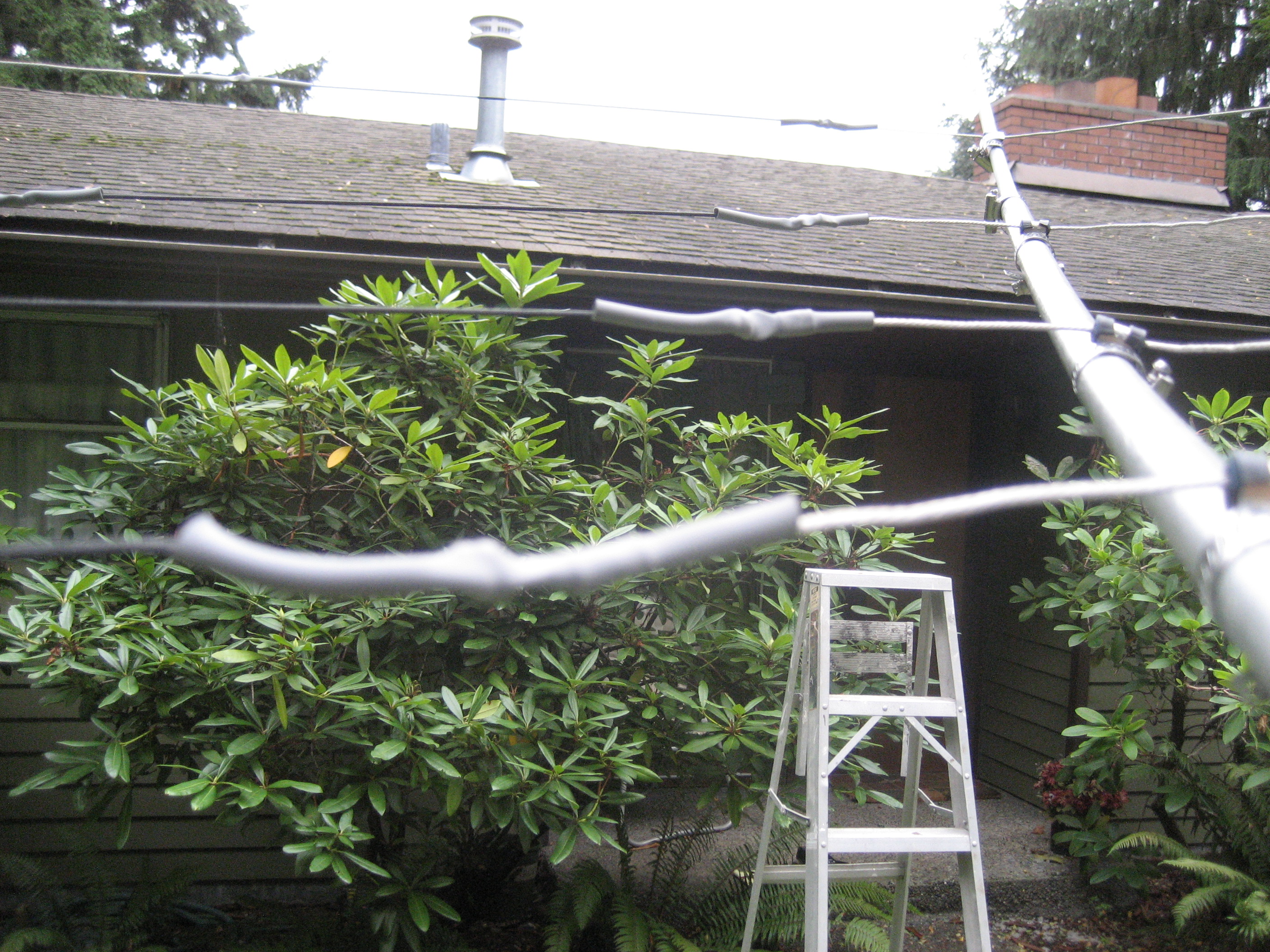
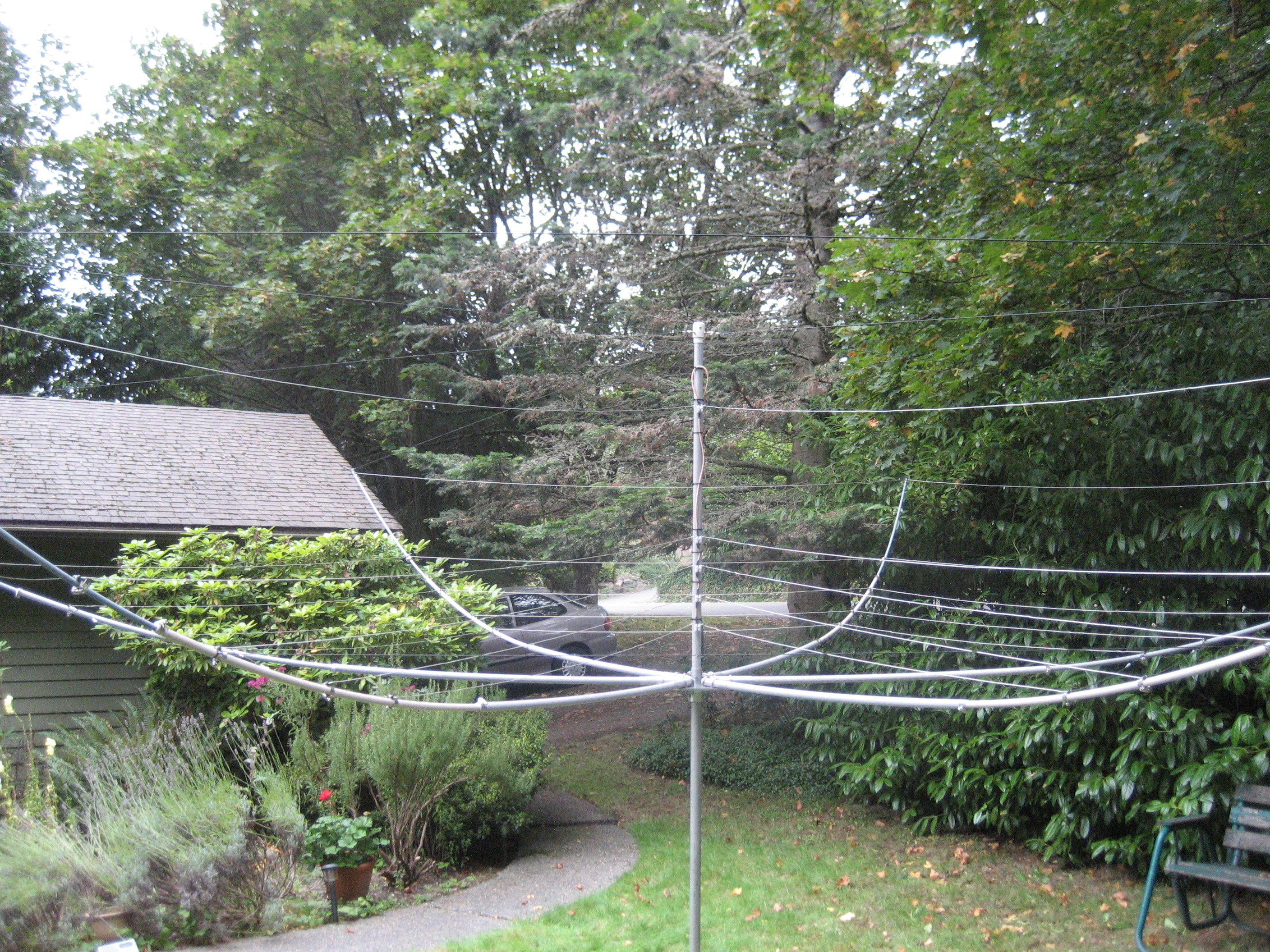
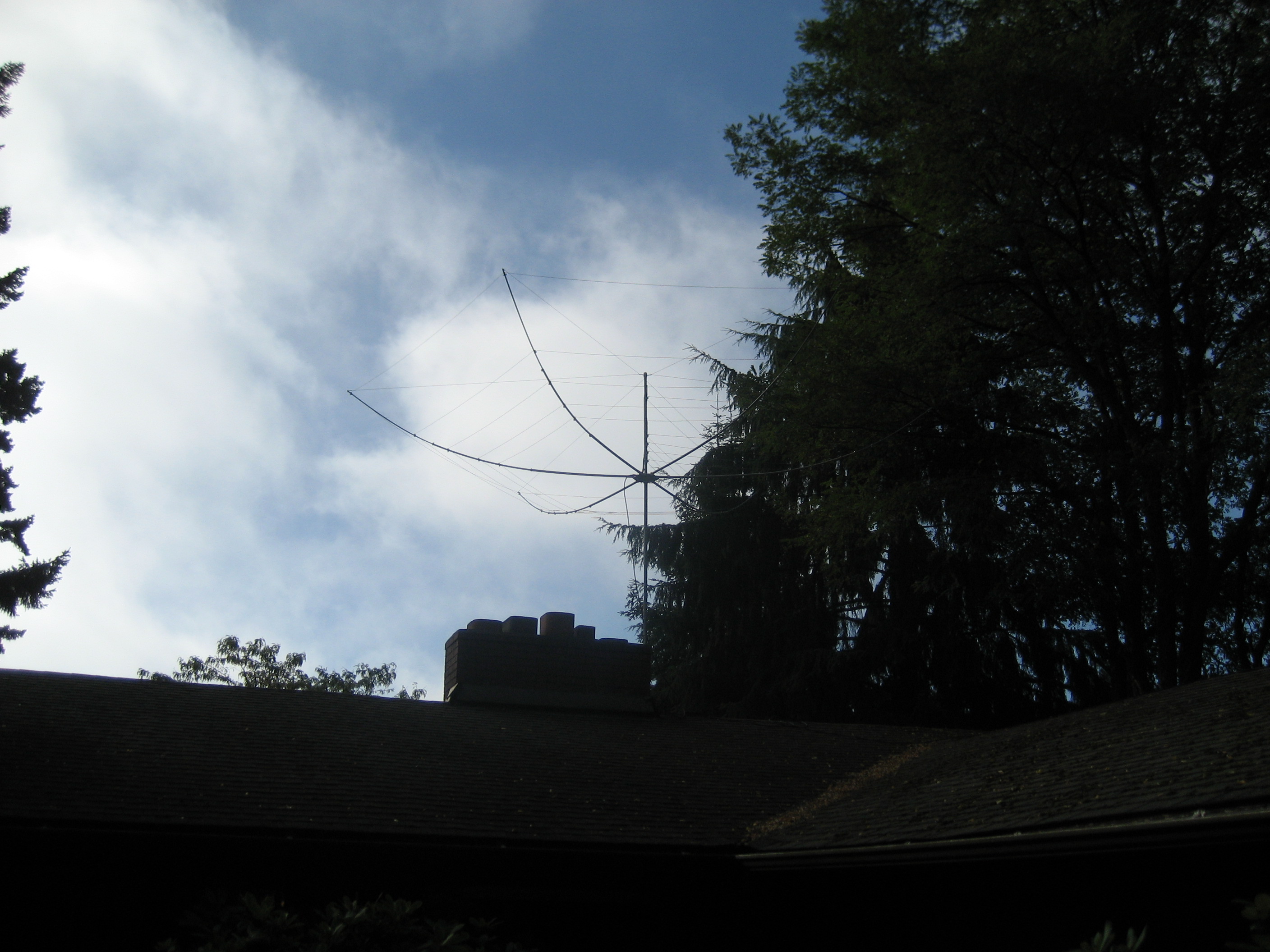
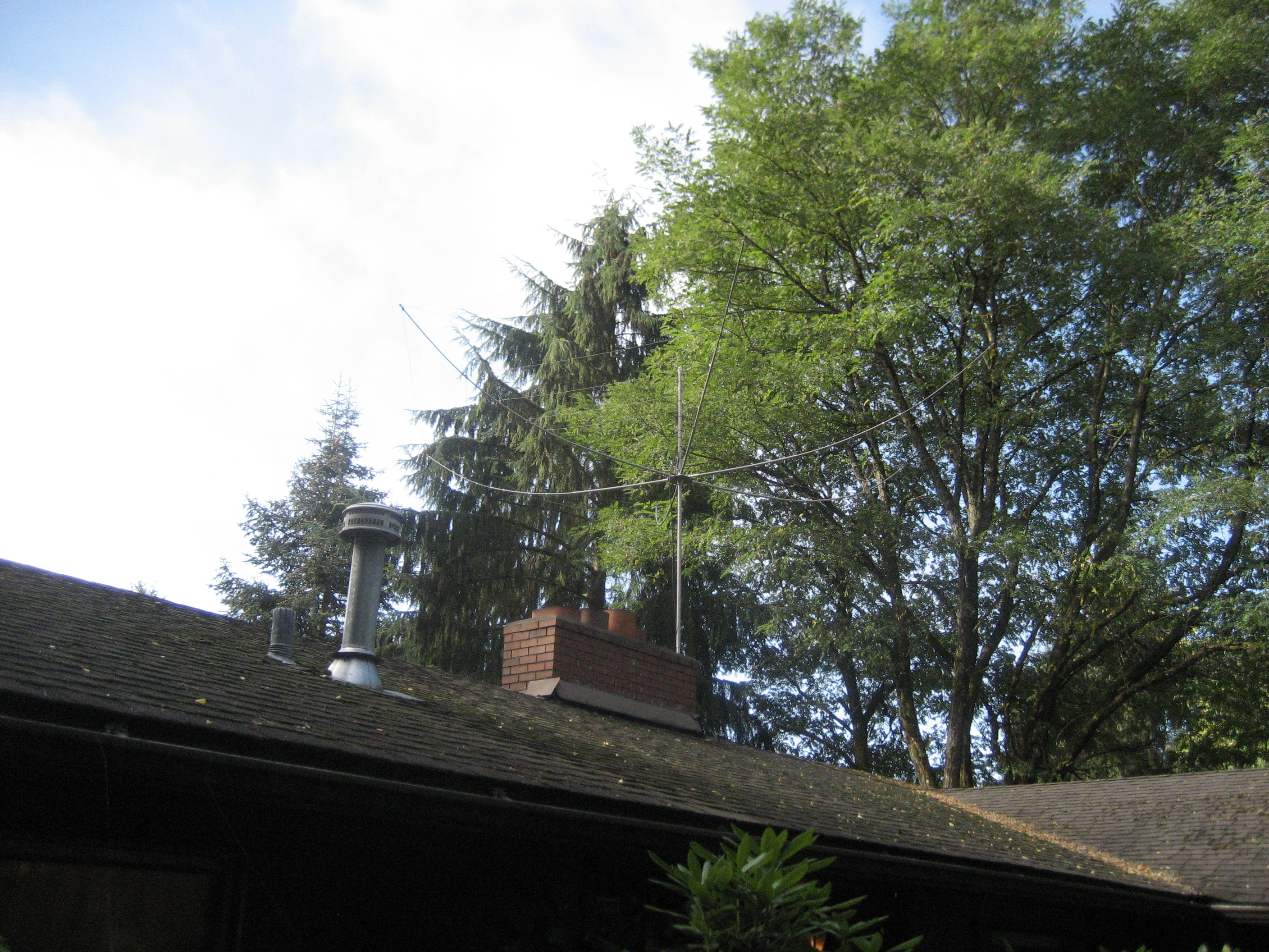
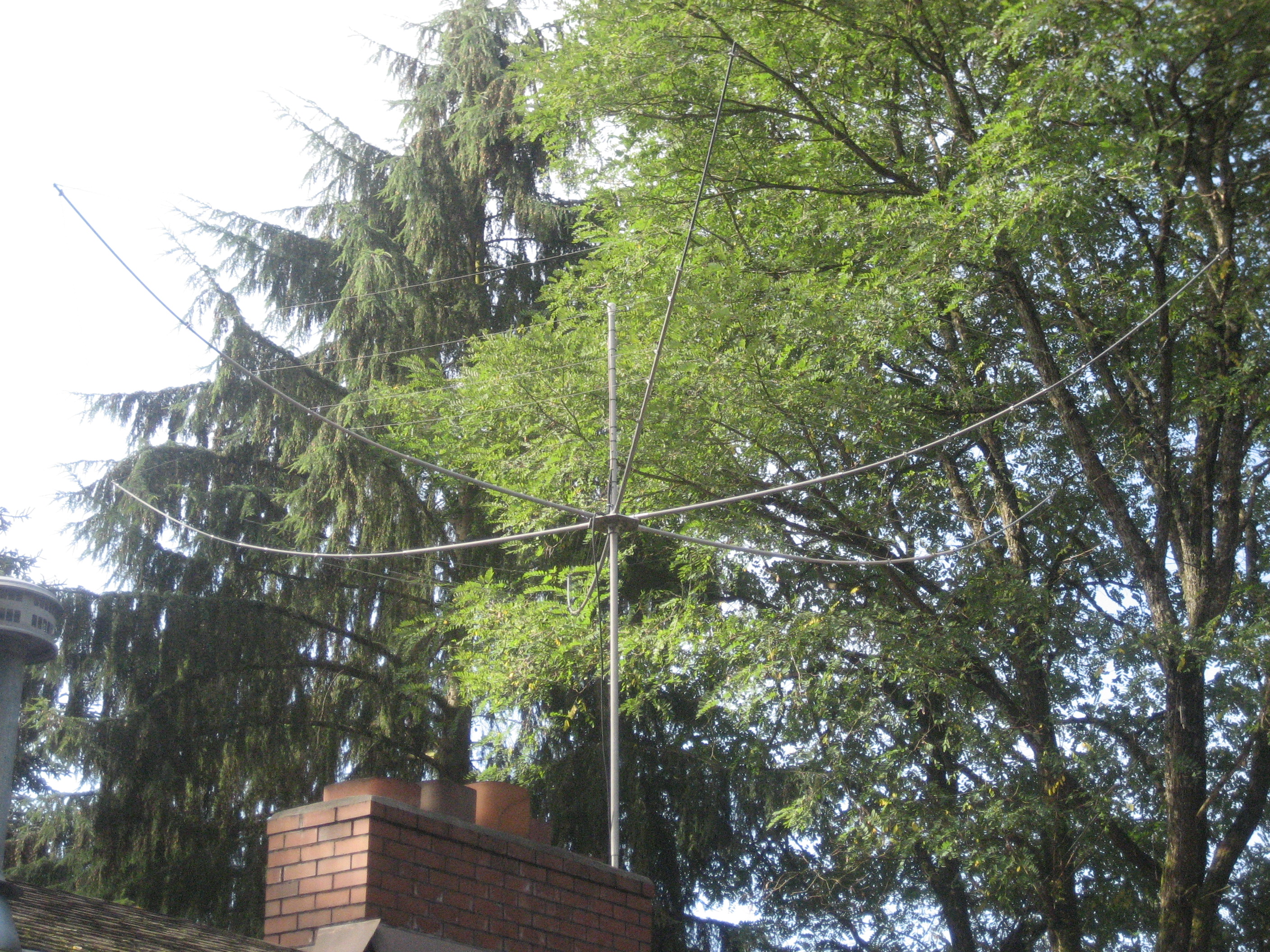
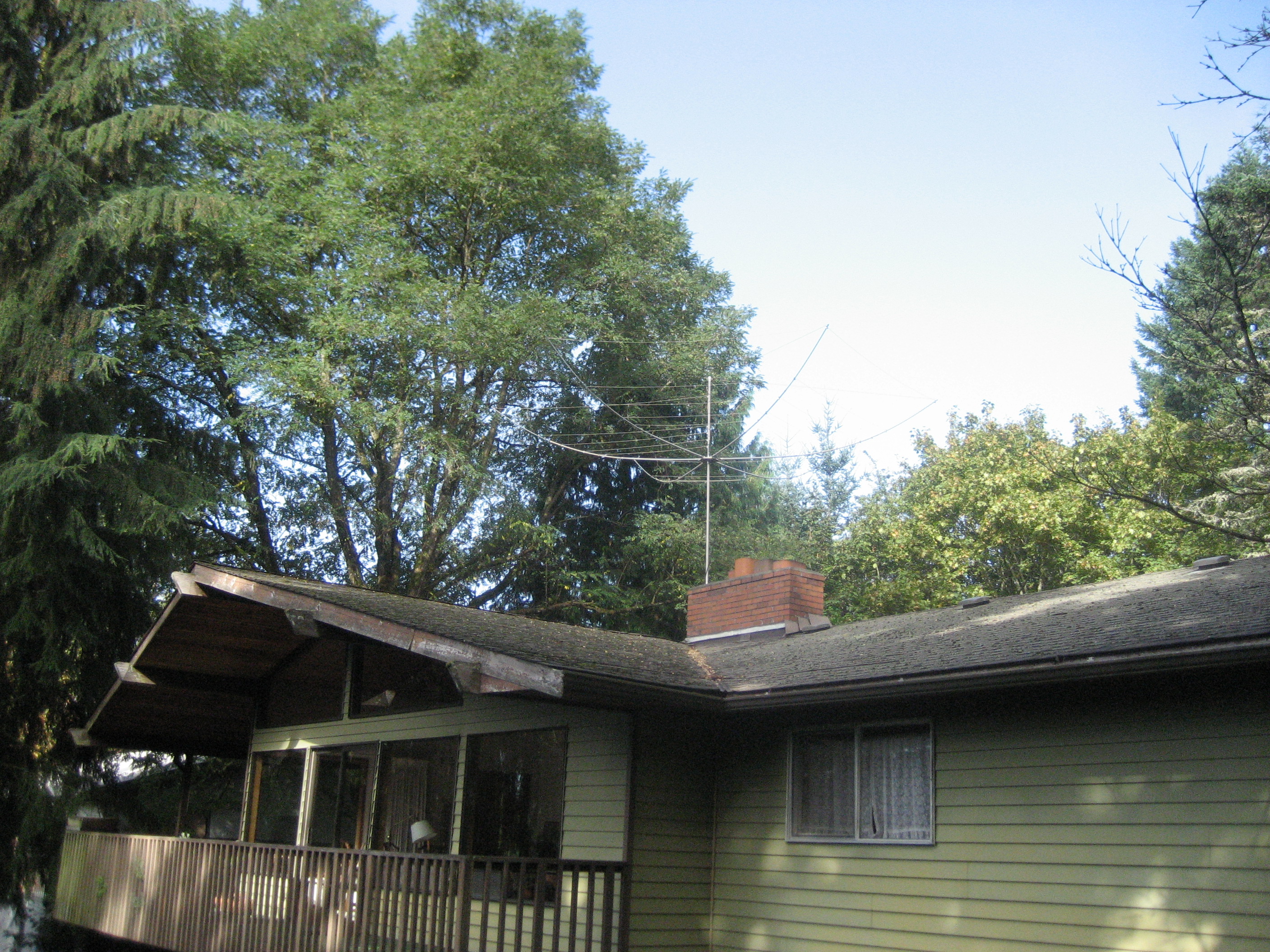
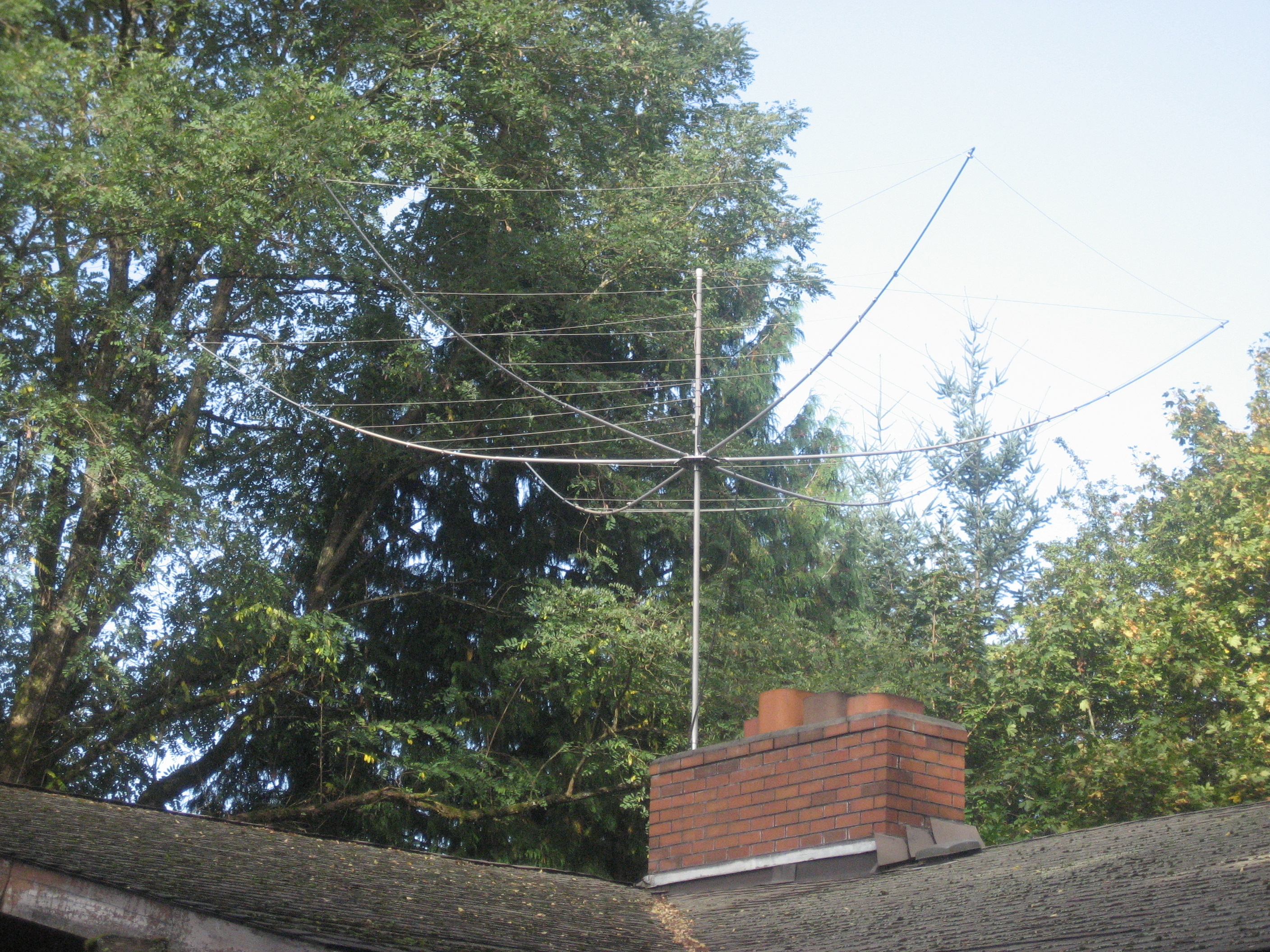
Here is the antenna installed on a temporary support. Later on, it will be moved to the chimney facing to the left, with a rotor I operated this way for a couple of months before getting a rotor and building a support structure. Rotating the antenna meant getting a ladder out and climbing the roof.